This smelt is the third in the series working to re-create that which took place at Vinland (L'Anse aux Meadows) circa 1000 AD. This experiment is intended to be the last full systems test before the full dress rehersal (using all Viking Age tools and clothing) on June 12, 2010. To that end, one last significant historic equipment was added, a Norse style double bag bellows. The smelt sequence was based on accumulated experience, no clocks were used by the working team.
Team:
Iron Masters : Ken Cook & Darrell Markewitz
Charcoal : Sam Fallezone
Ore : Neil Peterson
Records : Steve Strang
Bellows operators : Dave Cox, Marcus Burnham, Sam, Ken, Darrell
Consolidation: Ken, Darrell, Dave, Sam
Site Layout:
Although this aspect will eventually be detailed in the complete paper, there are some separate topics listed in 'A Smelt for Vinland'. This experiment included a final placement of the various equipments as we expect to use for the full presentation smelt at L'Anse aux Meadows in late August, 2010 (tentatively August 22).
|
|
|
|
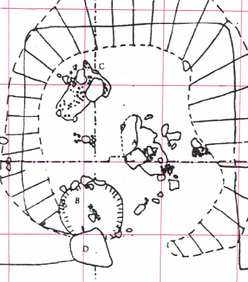
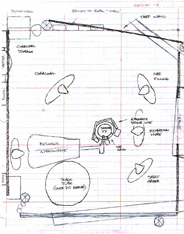
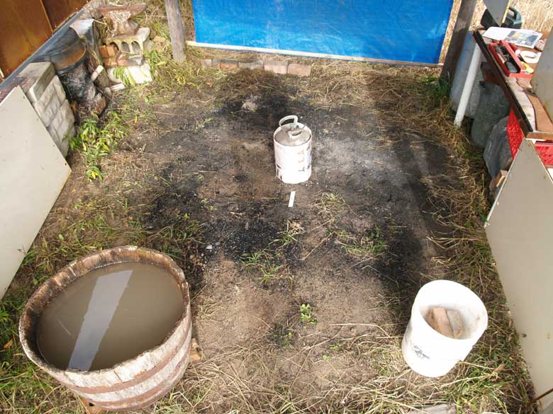
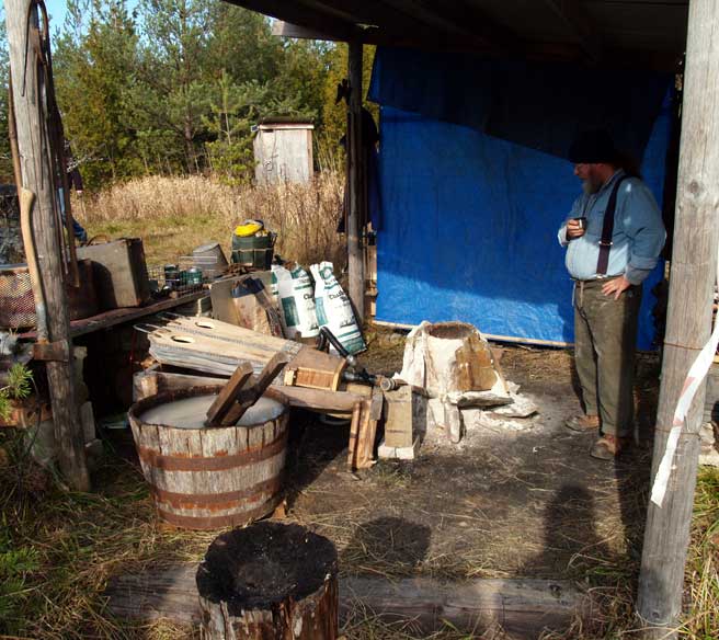
| Archaeological drawing of the L'Anse aux Meadows remains (1 m grid). | Layout drawing of the working area for Vinland 3 (1 m grid). | An elevated view, roughly corresponding to the Archaeological drawing. The metal cylinder marks the smelter. Slack tub positioned to duplicate size and position of an unexplained large pit from the archaeology. | After furnace construction, with major equipments in place. Several placements for the bellows were tried, this location to the left front was the only one that was workable. |
Furnace Construction:
The basic furnace construction was our 'Boxed Short Shaft' type. Based on a
closer examination of the published information about the remains at LAM, the
material for the furnace walls has been changed for this experiment. (See also
a discussion on
available clay in the LAM area.) Course sand (dug locally) was mixed 50
/ 50 by volume with powdered potter's clay (Bell Dark). The material was mixed
up with suitable water in large batches, then the furnace structure built up
by adding large slabs by hand.
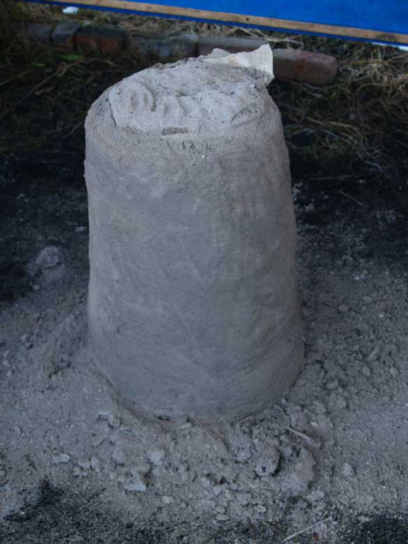
The finished furnace stands 55 - 58 cm tall with
walls roughly 5 - 7 cm thick.
 |
 |
 |
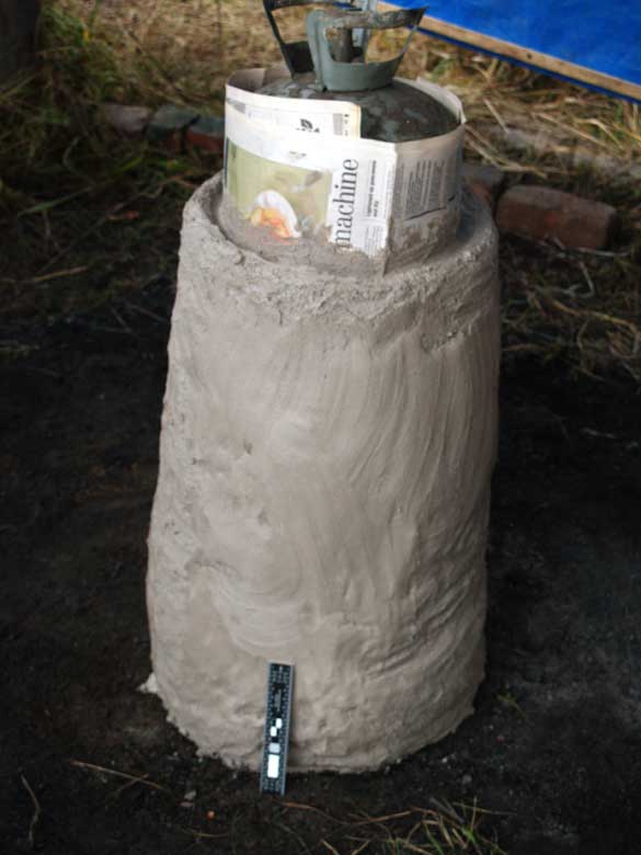 |
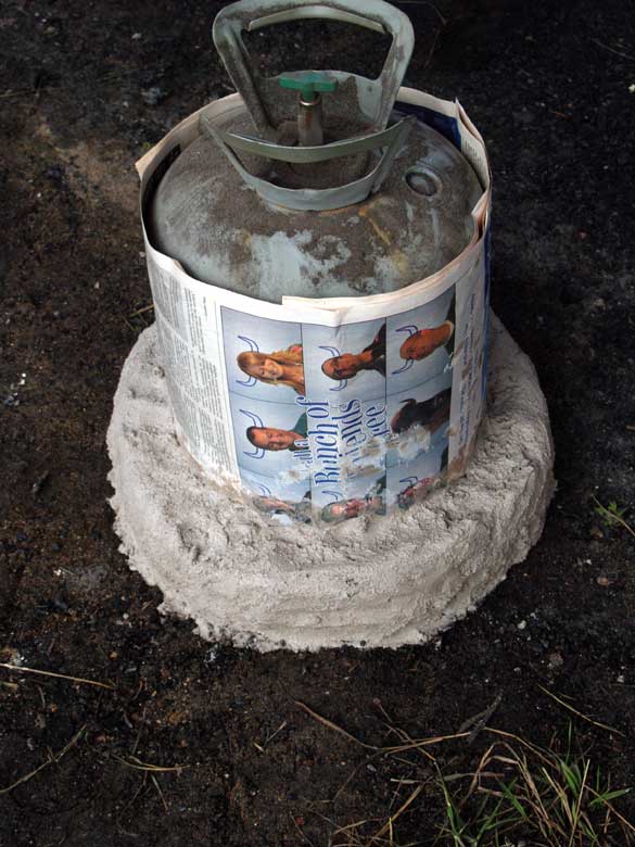
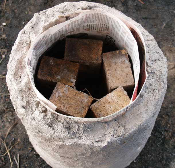
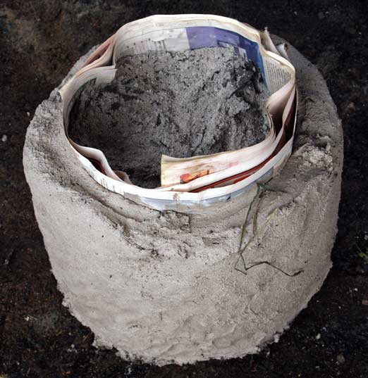
| Using a 22 cm diameter metal cylinder as a form. A layer of newspaper keeps it from sticking to the clay. Individual slabs of the clay/sand mix are formed, then applied and blended by hand. | As the cylinder is built up, the form is removed. A set of bricks is inserted, making a solid platform for holding up the form for the next layer of contruction. (Photo at end of second course.) | The remaining spaces are packed with dry wood ash. This both helps maintain the internal shape, it also helps to draw moisture from the wet clay. (Photo at end of first course.) | The finished clay structure, before final removing of the interior form. After is is gone, the furnace is filled with the ash, and the outside wrapped with a piece of sheet metal to prevent slumping. |
 |
 |
 |
 |
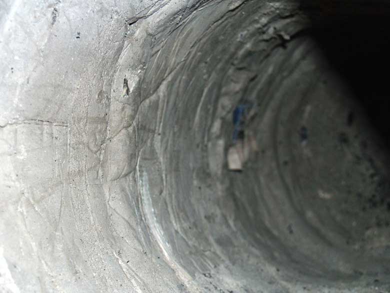
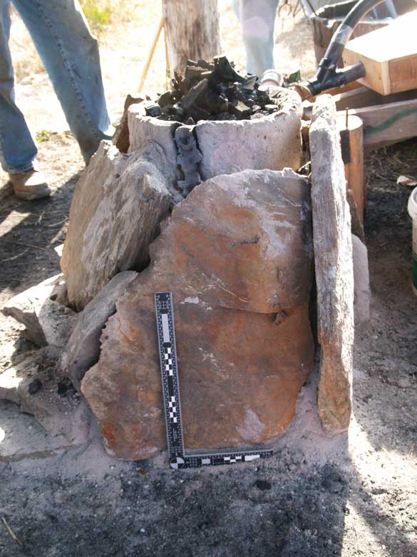
| After several days, with the metal wrap removed. The clay is still quite damp, but has stabilized considerably. | Interior, after the ash was removed and the damp paper. The ripples over the surface are a result of the hand forming process. | The furnace is finished with a layer of flat slabs around the exterior
to help support it. The gaps between are packed with the usual sand
& ash mixture. |
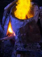
Front of the furnace, ready for the first full charcoal addition. To the left is the tuyere system, to the right is the stone blocking around a small tap arch. |
Air System:
The major variable in equipment for this smelt was the use of all human powered air. Although the mechanical box bellows from Vinland 2 was kept available, the air was supplied by the specially constructed smelter bellows. This unit had been bench tested with various operators earlier, and was expected to deliver the required air. Through the experiment, there was a rotation through a group of five primary operators (listed above). Each undertook a work cycle of about 10 - 15 minutes. They averaged 72 strokes per minute, delivering an estimated 700 LpM. A larger number of on hand observers also took a turn, but generally only for short periods as their output was very inconsistent.
The output of the bellows was linked to the tuyere by way of a thick leather 'Y' shaped coupling. This arrangement allowed for a straight line down the tuyere for observation and clearing the air pathway. Past experience had also proved the leather creates a flexible coupling, keeping vibration from the bellows action from being transmitted to the furnace.
The tuyere used was forged from standard schedule 40 mild steel pipe. It was 1 1/4 inch interior diameter reduced to 2 cm ID at the furnace side.
Air Specifics:
ID at tip - 2 cm (starting)
Projection to interior - 5 cm
Height above hard floor - 15 cm
Tuyere angle - start at 22.5 degrees down, later adjusted to 30 degrees down
Tap arch - 27 cm wide X 15 cm tall, about 45 degrees to right
Stack Hieght (above tuyere) - 40 cm
 |
 |
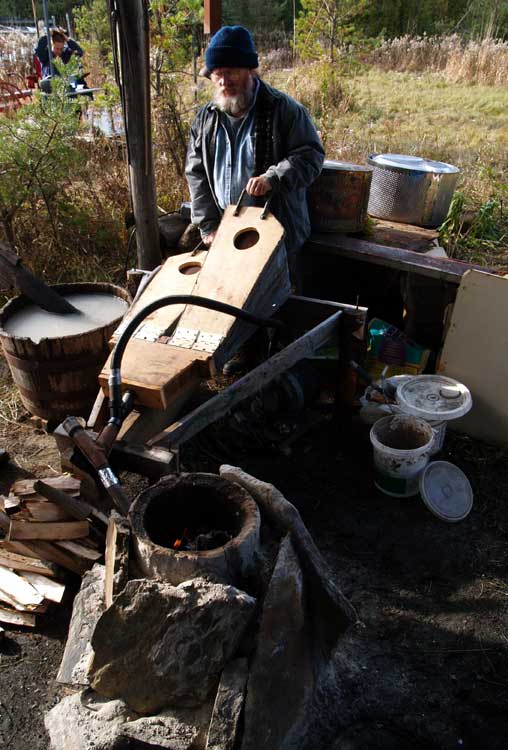 |
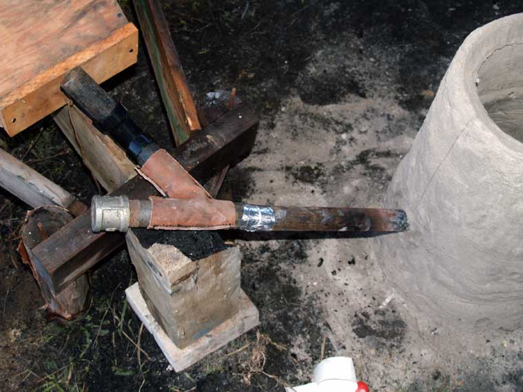
| Detail of the leather Y coupling and tuyere. For this experiment, the frame built for the much larger 'UbberBellows' was used to support the bellows. | A view of the interior, after the installation of the tuyere, and just at the end of pre-heat. The tuyere tip can be seen extending proud of the furnace wall. This view corresponds to the inside view above. Note the large cracks from the drying process. | Ken at work on the bellows. The frame supports the bellows to put the handles at the ideal position while standing. Again past experience has shown that working standing is easiest for the worker. |
Smelt Sequence:
Ore
- DARC Dirt 2 analog (about 65 % Fe)
- 18 kg added
- Basic charge was 1 kg, added by 'standard scoop' at approximately 250 gm
Charcoal
- Graded to normal ' golf ball to pea' size (through 2.5 and .5 cm grids)
- Basic charge was 2 kg, added by 'standard bucket'
The use of a steel pipe (standard 1/8 wall thickness) always results in erosion
of the tuyere. Typically, this works back to the furnace wall, then causes significant
erosion of the furnace wall itself. This was extreme in this case, the wall
immediately around the tuyere was egg shell thin (about 2 mm) by the end of
the smelt. At one point the wall burned through and had to be quickly patched.
Continued use of our standard ceramic tuyere would certainly have avoided this
problem. Forming a protective cone of clay around the pipe where it projected
from the furnace would also reduce errosion.
The specially built 'smelting bellows' proved both easy to operate and able
to produce volume required. There appeared to be some problem maintaining the
correct pressure. Lower force levels used by some bellows operators resulted
in an obvious shifting of the heat zone both towards the tuyere and also further
up from the bottom. This in turn caused the slag bowl to sit higher and closer
to the front than is ideal. Some problem with a shallow slag bowl attempting
to drown the tuyere resulted, requiring tapping / modifying bowl position, especially
early in the smelt.
The most obvious solution is better training for the bellows operators to allow
for more consistent air delivery. (This was our first use of human powered air
since our very first attempts, some years ago. Many of the operators 'taking
turns' had no experience with any type of bellows at all.)
Increasing the angle of the tuyere slightly was found to help with lowering
position of the developing slag bowl.
 |
 |
 |
|
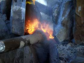
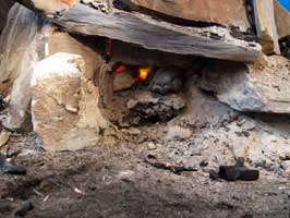
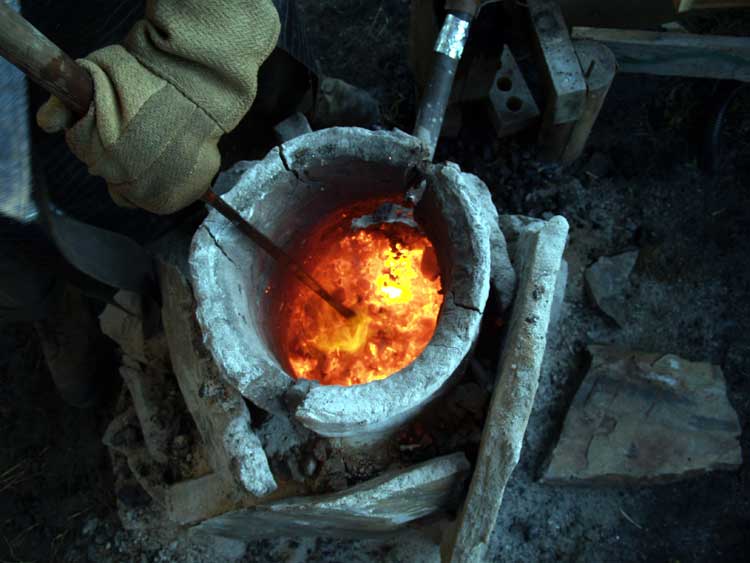
| About half way into the main sequence. The wall around the tuyere (the normal hot spot) was obviously erroding excessively. This image shows the clay glowing bright orange, with small areas completely burned through to the left. | Pulling the tap arch open to expose the bottom of the developing slag bowl. This was judged to be too high, risking drowning the tuyere. Here a hole has been made with a probe through the side of the bowl, and the first runnel of liquid slag can be seen starting to flow. | Late in the smelt, just before extraction. The damage to the front of the smelter is obvious. | A short video segment covering aspects of the smelt. |
This smelt also marked an absence of one modern aspect - time. In past experiments,
elapsed time has been the main control point for our actions. For this smelt,
a consistent air flow was established, and a set of standard measures for charcoal
and ore used. The pattern of ore to charcoal additions was based on past experiences
(rather than being modified to suit elapsed time). This did not appear to present
a major problem, as the team has accumulated enough experience at this point
to utilize other cues (primarily sound).
One thing that did become obvious is that some counting method is required.
Over the long course of a smelt, things like 'how many buckets since...' and
'how many ore scoops so far this bucket...' become difficult to remember. A
simple set of stone counters is the suggested method for keeping track.
It was clear that the end segment of the smelt sequence was rushed slightly.
It was decided to merely cover over the last ore charge added with a partial
bucket. The reason for this was the extreme fragility of the eroded sections
of the lower furnace walls. In the end it was found a significant amount of
reduced metal did not have time to adequately attach itself to the developing
bloom. This resulted in the loss of a good 25 percent of possible bloom mass.
 |
|
 |
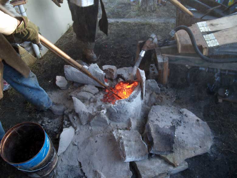 |
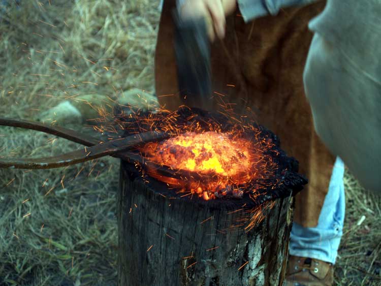
| Scopping out the last remaining burning charcoal. | Using the 'thumper' to compact the bloom in place, also helping to loosen it from the slag mass. | Inside the furnace, at point of extraction. The yellow hot bloom can be seen to the top of the interior. The tuyere is in line with the large crack at the same point. | Ken pulling the bloom, with its clinging layer of slag 'mother' out of the furnace. Note how difficulty extracting the bloom has resulted in considerable damage to the furnace walls. The clay/sand mix proved not as durable as our standard cobb. |
 |
 |
 |
 |
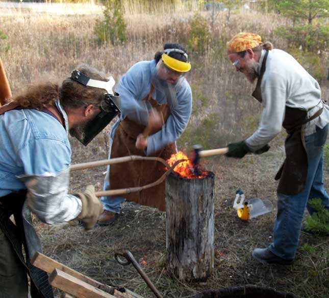
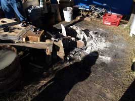
| Working over the mass on the wooden stubb. The first step is to knock off the slag mother and any lacy iron gromps. | Starting to compress the bloom. | At the end of the first consollation sequence. The visibly darker materal on the centre edge is attached slag. It cools much faster than the solid iron mass underneath. | Remains of the still hot furnace. It would be possible to charge fresh charcoal to use the furnace base like a giant forge. In truth the working team decided they were too tired to proceed with this. |
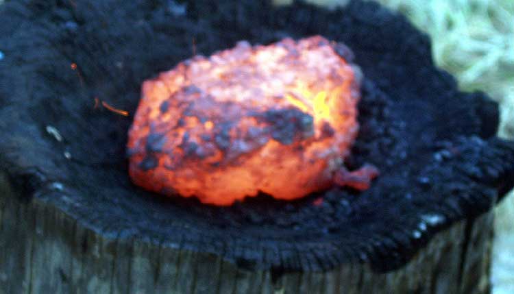
Bloom - 2.9 kg (after initial compaction after extraction)
further 1 kg of lacy metal was recovered (mostly too fine to compact)
Yield - 16 %
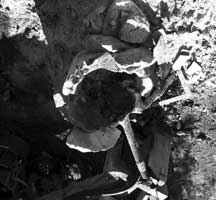
 |
 |
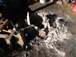 |
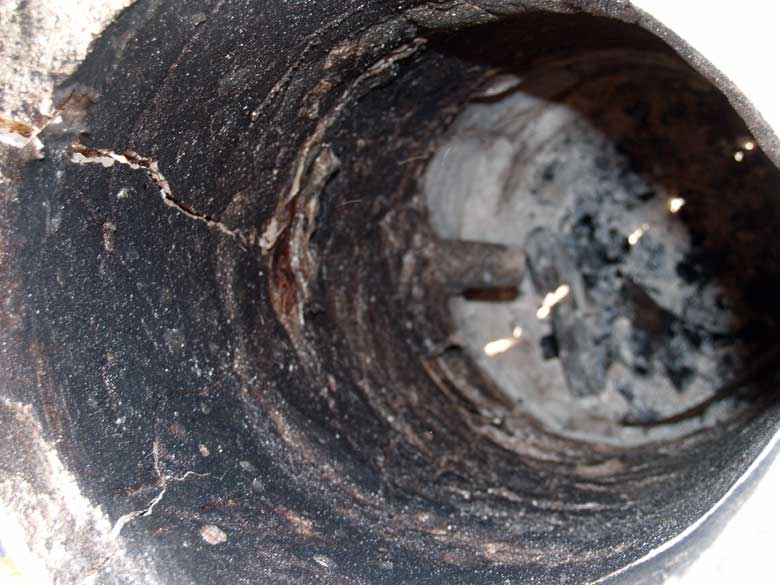
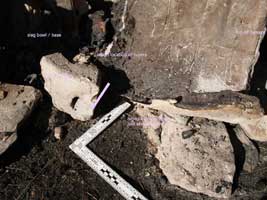
| The overall debris field, seen the following morning. There are spreads of charcoal to the left rear, ore to the right rear. Both indicate the location those activities. There was a clear void in the charcoal where the working was standing. Slag and gromps were spread to the right and front areas. | Furnace wall section from just above the tuyere. The scale sits in roughly the same line as the tuyere. The errosion of the wall is clear. The material just above the tuyere was no more than 2 mm at the thinnest point. | A close up image of the broken furnace itself. This image would roughly correspond to the remains of the Erlandsgard furnace (although the VA furnace is larger and more robust in construction). |
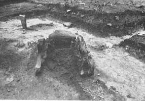 |
 |
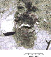 |
| Furnace remains at Erlandsgard, Norway. The grey mass in the centre is the large slag bowl. The walls appear to be a mixutre of clay andn small stones, and several large supporting stone slabs can be seen on the left side. | Vinland 3 furnace remains. The image has been converted to black and white and also rotated to match the image to the right. | Close up image of the surface level at L'Anse aux Meadows. The circles indicate my projection of the original furnace walls. |
Although there were some small problems with sequence, overall the experiment was a success. The use of the human powered air was less physically demanding than we expected. The team has accumulated enough practical experience that the loss of clocks was not a significant problem. The bloom produced appears to be soft workable iron. Although the yield is less than our normal, it closely matches the actual production by the Norse at Vinland which we are working to replicate.