Revised Air Delivery Test - Norse double chamber bellows - October 2007
Darrell Markewitz & Neil Peterson, raw data by Peter Martin


A series of tests were made by Neil Peterson and Peter Martin at the DARC smelt in Wareham on October 28.

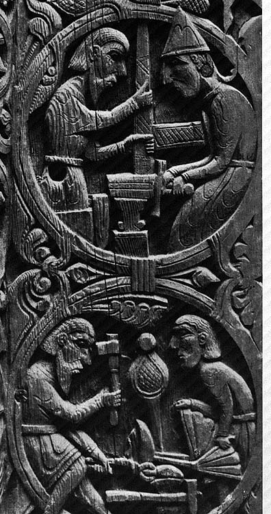
The bellows used is a reconstruction of a Viking Age blacksmith's double chamber bellows. The reconstruction is based on the two existing images of this type. The side depiction from Hylestad, Norway with a human figure provides relative scale, the top view from Ramsund, Sweden gives us proportions of length to width and valve size.
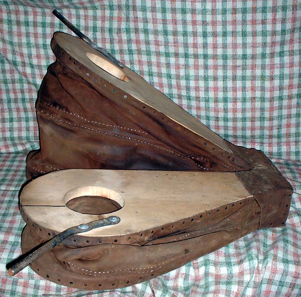
The rough dimensions of the reconstruction are: total length: 70 cm (28 inches) total width: 20 cm (20 inches) individual bag length: 50 cm (20 inches) individual bag width: 25 cm (10 inches) effective loft height: 30 cm (12 inches) inlet valve size; 10 cm (4 inches) outlet tube size: 2 cm For a fuller discussion of the reconstruction- go to an earlier BLOG Post
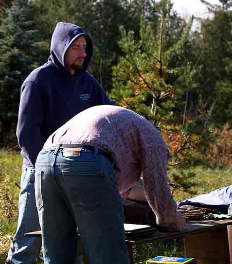
Measurements were made by Peter using a small hand held anemometer which would record an average flow over a time period of 20 seconds. Number of strokes delivered over the time were counted. This allowed individuals to develop a consistent pattern of strokes before the measurements were taken. The first control level was taken with the anemometer held over the exhaust tube of the bellows.

The tests were undertaken by a number of operators. The skill levels ranged considerably, from trained blacksmiths through to those who had never used any kind of bellows before. This was done to give the largest sample over the largest spread of skills. (It can be assumed that after several hours of working the bellows during a smelt, skill levels would come to be quite good - and air volumes more consistent.) It should also be noted that the Y tube running from the bellows was tied in place, but not sealed with clay. This would have allowed some seepage of air before it could be measured at the exhaust end of the bellows tube.

An attempt was made to estimate the effects of resistance such as that would be created inside a working smelter. Neil made up a simple filter was made by layering 'landscape fabric' into a wooden frame which could be placed over the bellows tube. Measurements were made while each operator pumped against one, two and then three layers of this cloth. (Note that there was no attempt to actually match these filters against the real resistance of a working smelter.)

L/min figures below assume a pipe with 2 cm interior diameter (18.8 is the resulting multiplier)
NAME: STROKES/Minute no pressure test
m/s (L/min)
pressure test 1
m/s (L/min)
pressure test 2
m/s (L/min)
pressure test 3
m/s (L/min)
Peter:
81
11.1 (209)
7.1 (133)
6.9 (130)
5.1 (103)
Kevin:
76
13.6 (256)
7.3 (137)
7.1 (133)
4.9 (92)
Neil:
75
11.7 (220)
7.1 (133)
7.1 (133)
4.3 (81)
Darrell:
69
9.3 (175)
6.3 (118)
5.5 (103)
3.2 (60)
Vandy:
108
11.2 (211)
8.4 (158)
7.5 (141)
5.4 (102)
Ken:
117
10.0 (188)
8.0 (150)
6.7 (126)
5.2 (98)
AVERAGE:
88
11.15 (209)
7.4 (139)
6.8 (128)
4.7 (88)

Observer's comments:

" As bag pressure increases stroke length shortens and stroke rate increases proportionately. Operator notes increased bag pressures and "maintains" "constant" pressure at bottom of stroke resulting in arithmetic decrease in flow rate at logarithmic increases in air resistance. " (Peter)
" Way too many math terms that I'm not sure truly apply - I'm very leery of the word usage here although I agree with the jist of the observation, pump rate goes up, stroke shortens and flow rate decreases. " (Neil)
With that said the pressure tester adds a theoretical geometric (or exponential) progression of resistance (0,1,2,4). (Theoretical as it may be that putting in two layers makes it 4 times as hard to move air, or only 1.5 times as hard as one layer.)
The drop off on flow isn't even close to that sort of progression. The drops are 33%, 8%, 31%. It is interesting that any resistance at all produces a very significant drop, doubling? that resistance then produces only a minor fall off, but doubling? again produces another hefty drop off. Perhaps we are approaching the limit of the bellows to move the air.
It was noted (Peter) that a more useful measure of resistance would have been produced by use of a graduated tube full of charcoal particles. Creating some method to introduce an anemometer 'in line' during a working smelt would also produce valuable information. (In the past all air volume measurements have been recorded with the blower venting with no resistance.)

In earlier writings, estimated values for the air delivered by this system were calculated by measuring the output of an earlier version of these bellows. This was done quite primitively, by means of attaching the bellows tube to a large garbage bag. Ten standard strokes were then made. The resulting bag of air was then placed inside a container of known volume, and the level compared to the total size of that container. This then produced an average volume produced per stroke at 2.2 litres. Working stroke rates were determined from actual operation of that same bellows by various (untrained) operators during the Early Iron 1 experimental smelt It was observed that the average strokes per minute over a working period of 10 minutes was roughly 1 per second. Taken together, these numbers produced an estimate of working air delivery set at 120 litres per minute.
In light of the better estimates produced in the test reported above, it is obvious those earlier volumes are incorrect. In effect however, at a working smelter producing considerable resistance to air flow, the original estimates still are close enough to the results of this test series. The earlier conclusions about the effective delivery of the Norse double bag bellows - in a size indicated as blacksmith's equipment, remain supported.
This article is reformatted from an earlier report posted to 'Hammered Out Bits'
Text and photographs © Darrell Markewitz & Neil Peterson, 2007