Reconstruction based on Hals
Team :
Smelt Master - Richard Schwitzer
Lead - Neil Peterson
Assist - Darrell Markewitz
Labour -
Eric, Brandon, Nathan
Records - Vandy Simpson
In a departure from the normal method, Richard
Schwitzer had volunteered to host this experiment, and
undertake the extensive build at his rural property at 4th Line
Amaranth. He so became the 'smelt master', the first time he had
attempted to organize the operation. Partially this was done
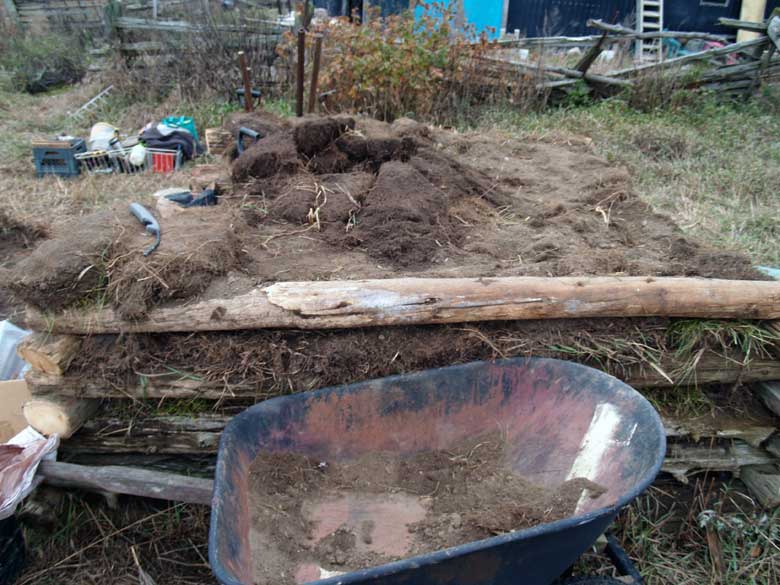
because he had the ability to lift the large amount of grass sod
required for the full build.
Reconstruction based on Hals
 |
 |
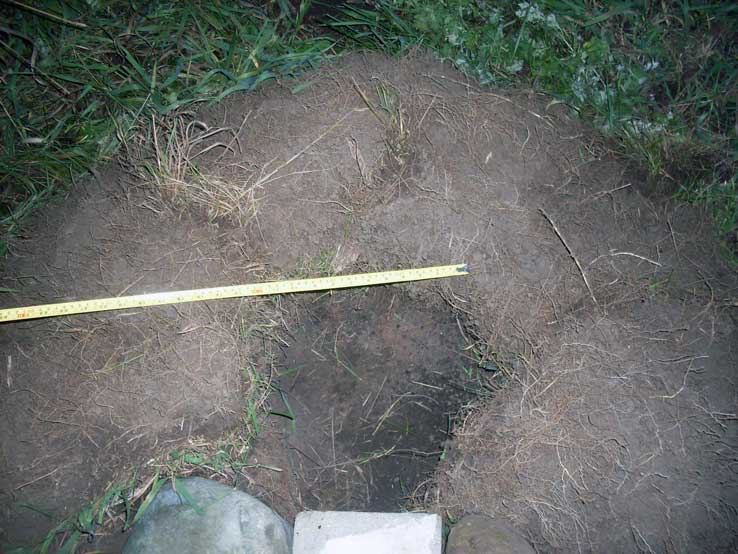
| Base layer of grass sod (RS) |
Initial placement of stones
for tap arch (RS) |
Because Richard had undertaken the construction process over some
time, the descriptions are less complete than normal.
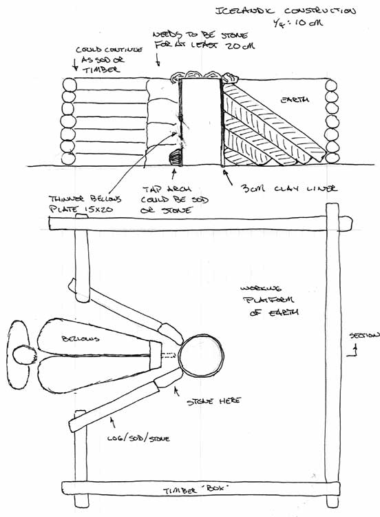
The general form of the suggested re-construction for Hals (seen
above) was followed.
 |
 |
| Completed Structure
(lines at about 30 cm) |
Side view (front to left) |
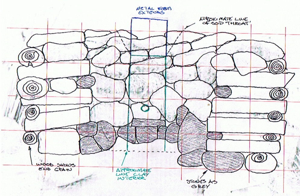
The drawing above is a reconstruction, based on the front view
image. The grid overlay is roughly 30 cm spacing, using the milk
crate seen in the original photograph for scale. There is
certainly some distortion, due to the angle of the photograph.
One of the things clear in the photographs is that the sod layers
are stacked flat (like bricks), not the diagonal lines seen in the
archaeology at Hals. The overall width of the log framing was
never recorded, but appears to be roughly 220 cm, and about 100 cm
tall. The sod layers are seen to extend beyond this, about an
additional 20 cm.
 |
 |
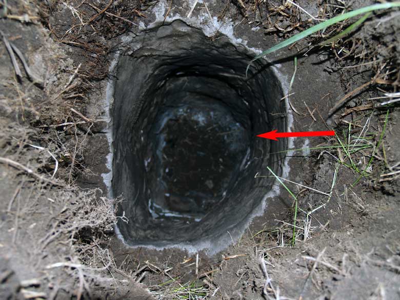
| Furnace interior - arrow marks
tuyere. Note sloping 'throat' at top. |
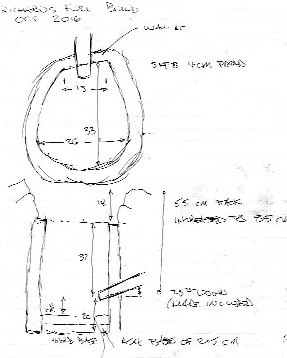
My (rough!) field drawing of
the interior |
Chamber size at Tuyere : 33 cm (front to back) x 26 cm (side to
side)
Total furnace Height : 57 cm as clay
Shaft Height above Tuyere : 37 cm (starting height)
Wall Thickness : reported as '3 cm' (image above suggests closer
to 5 cm)
Height of Tuyere above base : 17.5 cm (as set at pre-heat)
Tuyere : standard forged copper / 2 cm ID
Tuyere angle : 25 down
Tuyere placement : 4 cm proud
The normally recorded smelt squence
notes proved a lot rougher than the normal (I had some
trouble formatting these).
Neil Peterson had recorded some observations on the DARC
Iron Smelting documentation, (which I have borrowed heavily
from):
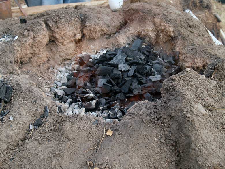
Preheat was a bit rough which spalled a lot of the clay lining off. This caused immediate problems with the slag bowl forming high. It also caused longer term problems with excess slag from the sand in the dirt of the sods dropping into the furnace.
As a result (of cold weather after construction), there was massive spalling right from the start during the pre-heat, even before we switched to the charcoal. Twice we opened the bottom to remove partially slagged ceramic material. Fortunately, this was before we had started adding ore, but even after, it took a long time before things stabilized. Two more times we had to open up the bottom to try to lower the bowl and/or tap the slag. We also were constantly battling to keep the tuyere clear as slag froze over the opening. As a result, there were multiple interruptions or reductions in the air flow.
The sequence notes show a pre-heat of only 55 minutes, before the
furnace was filled with charcoal, with a full volume air
blast was applied. The industial blower standard for our smelts is
rated for 1400 LpM, normally the air volumes used in previous
smelts are reduced to the range of 800 - 1000 LpM maximum. In
retrospect, this quick application of high air / temperatures
would have been expected to result in massive spalling of the damp
clay (which past
experience certainly has illustrated).
I suspect this resulted in virtually none of the initial thin clay
lining to have remained by the time the interior charcoal had been
emptied out, clay fragments removed, then quickly replaced to the
furnace.
My own field drawing suggests that the effective base inside the
furnace ended up to be closer to 11 cm below the tuyere, by the
time the main smelt sequence was started.
 |
 |
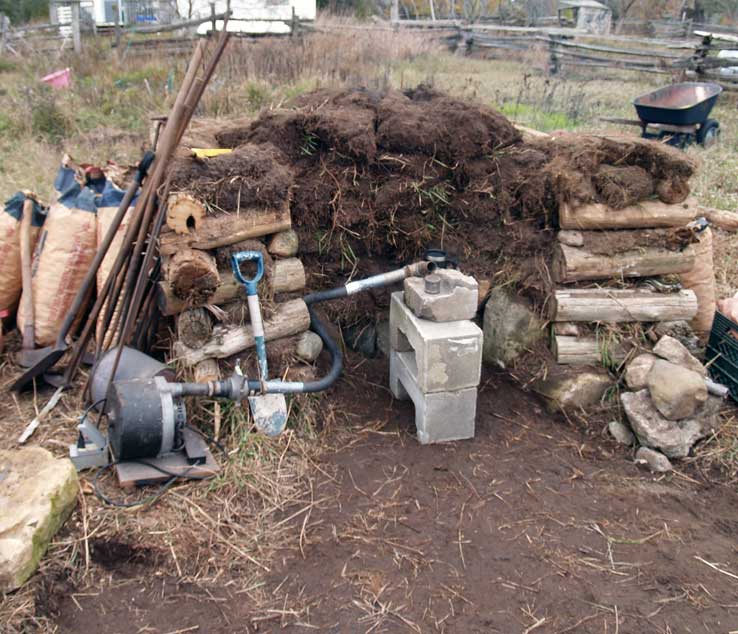
| Overall at the start - air
system in place |
Close-up of the tuyere
placement, showing extra sod cover |
The original mounting of the tuyere was supported on a stack of
blocks. This would (somewhat) echo the placement of a bellows
during the Viking Age. This would prove a problem, as the stone
blocking the tap arch had to be pulled clear and the lower part of
the furnace scooped out to clear the broken clay pieces.
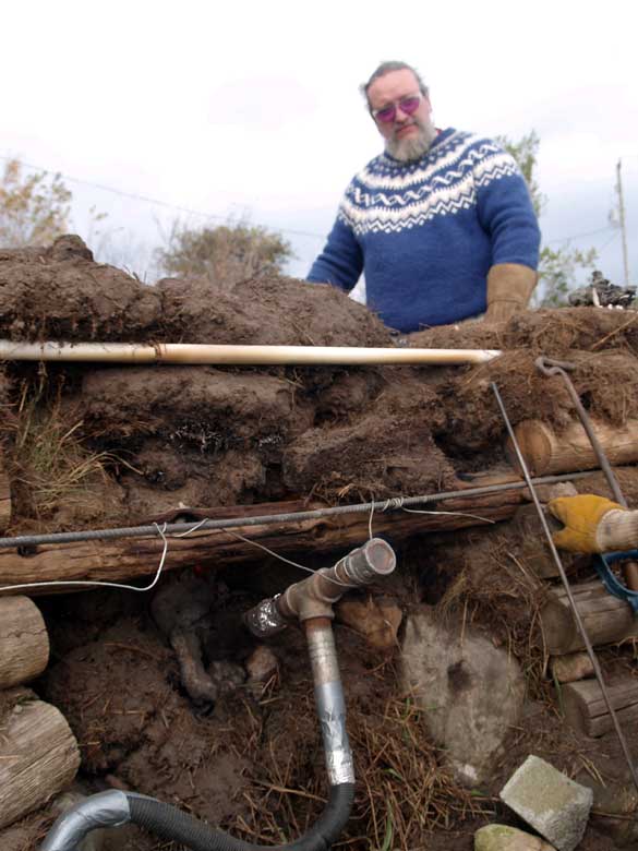
Eventually the tuyere and piping system was hung from a pole
across the front of the furnace.
There is a cryptic note on the field drawning '55 cm stack /
increased to 85 cm'. This may refer to adding a cylindrical metal
collar to the top of the furnace to extend the stack height. In
truth there is nothing beyond this note, none of the existing
images show this piece in use. There is certainly significant
crumbling away of the working top edge of the furnace seen. The
starting stack height (from the clay liner) was already marginal
(at 37 cm), 40 cm is considered the minumum effective distance.
 |
 |
| Neil, working from outside
timber frame |
Errosion a the mouth of the
furnace |
The interpretations of the furnace build used at Hals (in the
excavation report by Kevin Smith, and my
own evaluation) suggested a flat working area around the top
of the furnace. There were two functional reasons for this :
In practice during this experiment, it was found that the long
handle equipped bucket and scoop normally used for these additions
were certainly easy enough to control when still standing on the
ground outside the timber frame. (The handles had been added
originally just to protect workers from the high temperatures at
the top of the furnace.)
The question of how to effectively incorporate a bellows into the
same
space used for slag tapping remains unresolved. Our use of
of plastic hoses to channel blower supplied air means we have not
had to deal with this problem yet.
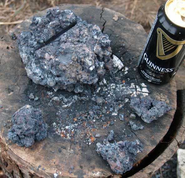
There are two different accounts of the resulting bloom. I
suspect the higher number of 3.2 kg includes the fractured pieces
seen in the image above. This suggests the lower number of 2.5 kg
more accurately reports the true weight of the bloom mass. Taken
against an ore about of 25 kg, this represents only a 10% yield,
significanly lower than other smelts in this series.
Neil also reported :
The soil in the area is very sandy. This seems to have created several problems. Firstly, the grass root mass penetrated deeper into the soil, but without much density. This lead to some structural issues during construction, and there were real concerns of the exposed front wall collapsing during the smelt. Secondly, there was no sintering of the soil which might have happened if there had been a higher clay content. Concerns over structural integrity led to a log and later a pipe being added, along with several sod blocks, but the threatened collapse of the front never did materialize. Much of the credit goes to the stone lintel over the tap arch which played a big role in stabilizing everything as we fought with the slag. The addition of extra sod blocks at the bottom did a good job of controlling unwanted jets of flame without too much extra effort, with the added bonus of being easy to remove when necessary.
Taken together, the combination of spottty record keeping, marginal furnace design, problems with working sequence, all suggest that this experiment should be at best considered a 'proof of concept'. The overall test of a full build based more closely on the archaeology of Hals should be repeated.