A Work in Progress
Railing in Riverdale - Toronto
2007
Project Description - step by step
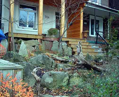
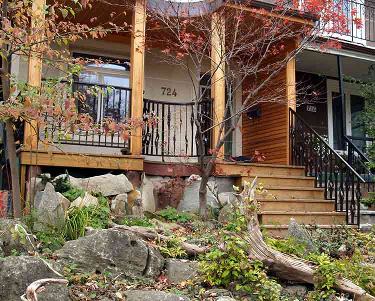
I was contacted by a couple who owned a renovated early 1900's home on a quiet street a couple of blocks from the site of the old Riverdale Zoo in Toronto. (Just east of the Don Valley - south of Danforth Ave.) They had been working away on landscaping and designing a new front yard and entrance on their home. The original porch and its overhead roofing had been totally replaced. The new construction was of rich western cedar planking and beams, with the roof sheathing of copper sheet. A special feature was a tree planted years before. The new extended deck line was cut away in a half circle to preserve the tree. The landscaping was done to echo the natural features of more northern Ontario, with large stones forming irregular levels in place of a series of static retaining walls. As you can see from the images below (taken in March) the front door is about four feet from the top of the yard - itself another three or four feet above sidewalk level.
| A view of the house from the sidewalk, approaching from the south. |
|
|
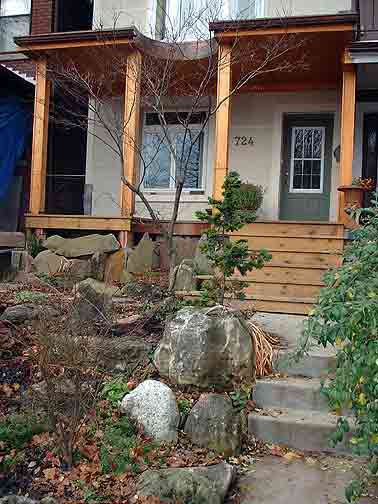
A view of the house from the start of the front walk in. |
The Clients had contacted me after seeing the work exhibited here on the Wareham Forge website. A primary concern was having a design that reflected the overall natural feeling that the other elements of the landscape and deck had established. Stict adherance to the building codes was less of an issue, but the adult owners did want the railings and handrails to be safe and sturdy. One important factor that had to be considered was maintaining the view from the large and low mounted front window across into the park on the other side of the street. On the technical end, one railing unit would have to be curved in a half circle to fit around the deck cut out for the tree. Also the hand rail on the left side as you face the house had to fit the irregular curvature of the stairs on that side. All of these requirements had lead them to contact an artisan blacksmith for an original art design for their project.
After some initial conversations over e-mail to frame the project and establish a rough budget, I visited their home. This allowed me to get a feeling for both the established work and also a sence of the couples tastes (and general outlook!). We looked at some photographic references and talked over some general concepts towards possible designs. Some ideas were disguarded at this stage, and I was able to leave with a handfull of notes and some marked images of historic metalwork for reminders of what they liked. Also a set of detailed measurements of the installation area was made.
The next step was the generation of a number of potential designs. First the measurements were converted into a set of scaled drawings in plan and elevation. This would allow each of the potential designs to be drawn in the correct proportions. One suggestion originally kept in mind was to try to incorporate solid copper into the metalwork, to better integrate with the copper roofing and flashing in place. It was also decided to paint the finished metalwork a dark brown as opposed to the more standard black. You can see from the roughs for potential designs I created for the project, There were three main themes - a 'wheat sheaf' with a central copper element / sweeping lines based on a stylized bull rush / a more conventional layout with large copper washers. The order that the ideas came to me are shown below - and may prove interesting.
 |
 |
 |
 |
 |
 |
"Copper Sheaves" The main upright forged from 1" dia solid copper, flanked with two elements of forged from 3/4' dia steel. A wrap of 1/4" dia copper tube secures the middle junction with a frame of 2" wide flat stock. |
'Rushes' The main elements were tapered bull rush terminals forged from 1 1/4 dia pipe on 5/8" dia stems. Each weaves over a ribbon made of 2" wide flat stock. |
"Copper Disks" Each upright forged from 1" square, then set on the diagonal. Two strips of 2" wide flat weave accross. At each junction point is placed a disk of solid copper. These are textured hot using the peen of the hammer. |
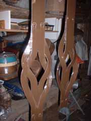
As is common in so much of my work, the intial design, which often comes in a flash during discussions, is by far the strongest. (Also my favorite!) 'Copper Sheaves' features a stylized wheat sheaf design, bracketed by a series of large curves made of wide flat stock. Each of the central spires would be forged out of one inch diameter solid copper bar. Each of these was to be flanked by a pair of leaf like elements, forged down from a piece of 3/4 inch round steel. To balance the colour of the natural copper, the protective coating for the steel would be a dark brown colour (rather than the standard gloss black normally seen). At first the clinents were quite excited about this design - as they are of Ukranian heritage (Without realizing it, my own inspiration may have been ancient Roman use of simular elements.) Further examination of the graphic showed that a simular design was also stolen by the Natzi's during World War Two. With the neighbourhood having a fairly high number of older Jewish residents, it was thought that this design, how ever it had been concieved, might not be the best choice. A secondary consideration against this design was the considerable expense for large amount of copper that would be required.
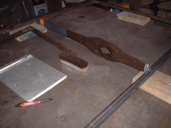
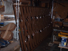
Creation of a full size sample piece
Although not as bold a design, the combination of tradtional lines with forged organic details represented by 'Copper Disks' was selected by the clients. Copper highlights were seen through the use of the large washers of copper mounted at each attachment point between upright and the two weaving horizontal bands. Each disk would be cut as a roughly 3/8 inch thick slug off the end of a long solid copper rod. Then each would be agressively hot forged using the peen of the hammer to create a series of deep radial lines on the metal surface. This design was chosen as the one to be used to create a full sized sample piece. On the sample the copper disks were replaced with 2 inch squares of 1/8 thick copper sheet (material I had on hand). The sample piece is an important bridge between the design drawings and the finished work. It allows the customer to clearly see the effect of the chosen design in place as it will be installed. It also serves as an example of the overall quality of the work to be expected in the finished project.
 |
 |
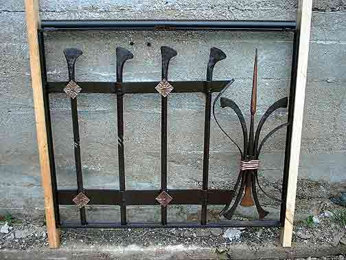
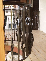
The completed sample piece was about 44 inches long, and mounted between two pieces of wood to show it at the same height above the decking it would be if installed. It also shows a variation on the design that became likely once the pieces were made - a small twist in the centre of each upright. I also made up a version of one of the primary elements from the 'wheat sheaf' design and included it to one end of the piece. The most likely destination for this sample length is installed at my own home. |
Prototype - "Copper Disks" |
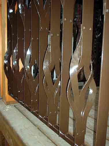
Detail of "Copper Sheaves" |
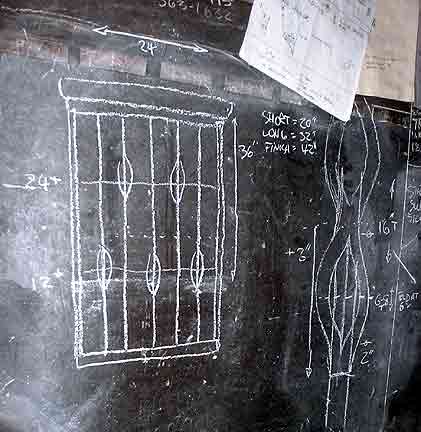
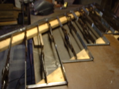
Early the very morning I had arranged to drive to Toronto and present this final design to the customer - I had a flash of inspiration while I laid in bed half wake. (Currious how often THAT happens!). Of course this was for an entirely different concept and totally different mannor of working the upright elements. I was able to verbally convey the rough concept, but it was clear that another full sized sample would be required to really illustrate the design. So from the idea in my head a very loose illustration was drafted on to the shop chalkboard (an extremely helpful thing by the way!) From this a total of five full sized upright elements were forged out.
 |
 |
 |
Original rough on chalkboard |
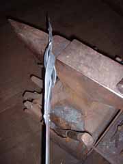
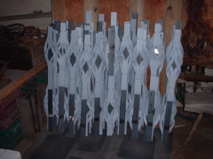
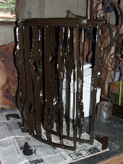
Secondary sample - "Weave" |
"Weave" - Close angled view |
There was always the problem of creating a design that the building codes might
approve, yet at the same time one that remained artisticaly interesting. The
starting point for this new design was a consideration of how to maintain clear
vision through the uprights from inside the house towards the park, but at the
same time creating some level of privacy from the street. Using a series of
thin flat bars, but set on edge to the viewer, would make the uprights almost
'disappear' optically from the inside window. Each upright retains its strength
from the 2 inch width of the bar - so the thickness could be reduced to 3/16
inch. From passers by in the street, the railing would be primarily viewed from
an angle. With the individual wide uprights spaced for the code required 3 3/4"
inch gaps, any angled view creates the impression of a solid wall of metal.
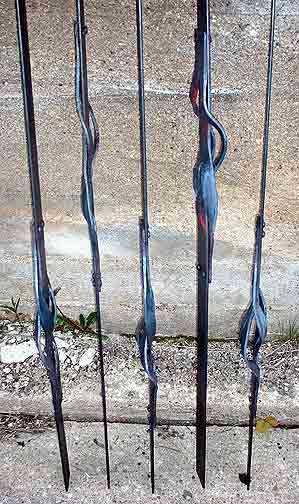
Each of the uprights is created from two pieces, cut to different lengths. Each
is folded, split, then opened up again to create a slighlty dished oval eye
near one end. The two pieces are then woven through each other while hot and
tapped flat and straight. The flat ends of each piece are secured with a total
of four oversized round head rivets, making the fastening a design element as
well. The uprights are positioned so that the forged weave alternates either
above or below the rough centre line of the completed railing. There will be
a certain random quality to each of the uprights, as the hand forged eyes are
deliberately made all somewhat different in exact shape.
It was possible for the clients to visualize how the completed railing using this new design would look - without them actually having a full sized sample piece in their hands. I had made up five of the upright elements, and using the images seen above was able to illustrate the effects of the design from various viewing angles. In the end the customers liked this new layout even better, especially as it showed the details of hand forging even better than their previous selection. The fact that this new design was basically within the demans of the building code was also a big factor in its final use for the project. A contract was signed and the deposit made. (It should be noted that despite the time spent on consulting visits, working drawnings, creating designs and many days fabricating samples - no actual funds changed hands until this point.)
Forging the Elements
 |
 |
 |
 |
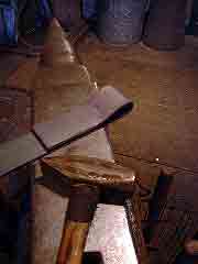
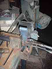
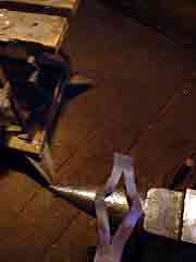
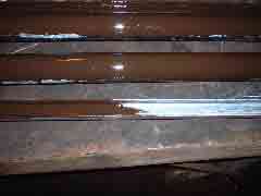
About 6 " folded over |
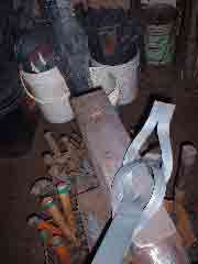
After cooling - longer pieces |
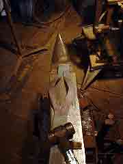
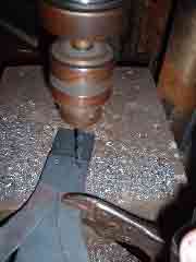
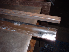
Slitting back 3" - using saw jig |
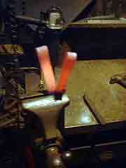
Spliting appart while hot |
 |
 |
 |
 |
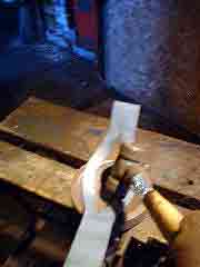
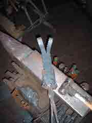
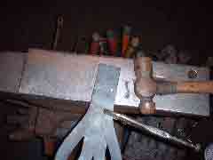
Forking to about 3" and flatten |
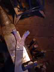
Opening up the fold A |
Opening up the fold B |
Flatten and Straighten |
 |
 |
 |
 |
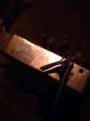
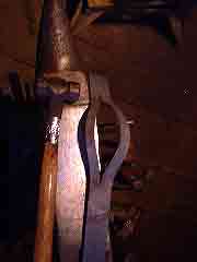
Dishing in Contour |
Bend tabs, curve for weaving |
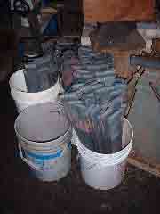
About 25 % done, at 15 per day! |
On short ends, work with tongs |
 |
 |
 |
 |
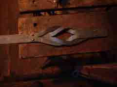
Interlacing pieces for fit |
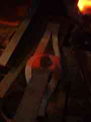
With heat, then tapping flat |
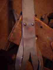
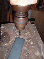
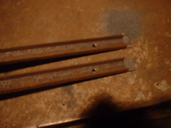
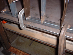
Drill two holes on one end |
Setting two rivets to secure pieces |
 |
 |
 |
 |
Adjust to fit, rivet other end |
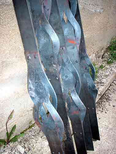
Interlaced upright element |
Heat and straighten to finish |
About Half Completed! |
Quicktime Movie - 'Forging the Uprights' 17 Minutes long Warning - 25 MG file! |
 |
 |
 |
 |
Drill hole on waste end |
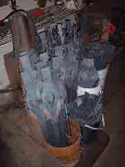
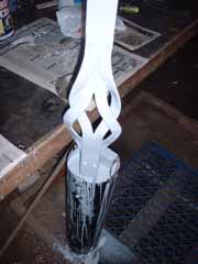
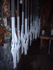
Dip in base primer |
Hang to dry |
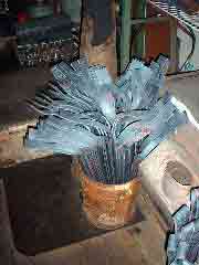
All 120 uprights primed |
 |
 |
 |
|
| Apply first colour coat - dry | Apply second colour coat - dry |
Next task is to assemble the panels... | Prime and paint inside handrail pieces |
 |
 |
 |
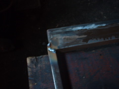 |
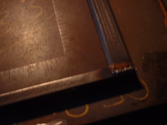
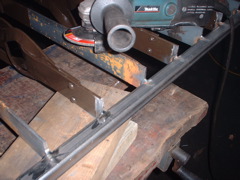
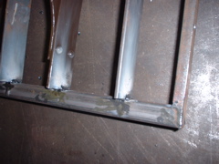
Weld hand rail to frame, grind smooth |
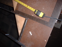
Cut and prepare side and bottom frame pieces |
Weld lower frame pieces into rectangle, grind smooth
(note square) |
Welding upper handrail into frame |
 |
 |
 |
 |
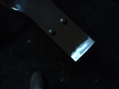
Sand clean paint off end of each upright to ensure
good weld |
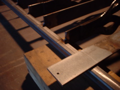
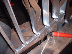
Layout positions for uprights, weld in centre unit |
Measure and cut each upright to fit, then tack weld
into frame |
Clamped to table, apply final welds |
 |
 |
 |
 |
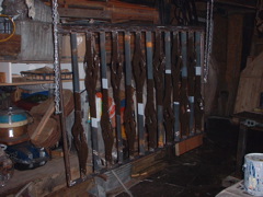
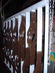
Grind clean original tack welds |
Assembled panel |
Prime unpainted areas |
Two coats colour - here finished panel |
 |
 |
 |
 |
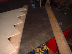
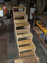
Layout stair outline and cut |
Fitting frame pieces for stairs | Lay in and tack weld uprights in frame | Arc weld to secure all joints |
 |
 |
 |
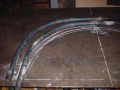 |
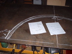
| Grind smooth the welds | Clean, hang, paint primer and colour | Laying out the curves for the half circle element | Forging the curved frame pieces to the drawing. |
 |
 |
 |
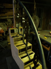 |
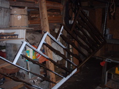
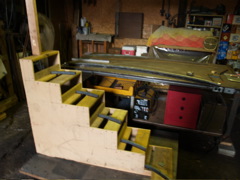
| Repeat the sequence of weld, grind, paint - the finished pieces | Build full scale mock up of stairs with side curve drawn in place | Handrail, support, lower frame all forged to the curve. | Starting to weld up the frame and upright elements on the mock up. |
 |
|||
| Welds and grinding finished. |
Final Installation
 |
 |
 |
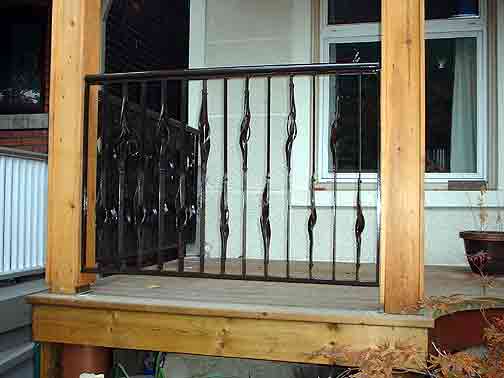
First two flat panels in place |
View from directly front |
Close angled view |
 |
 |
 |
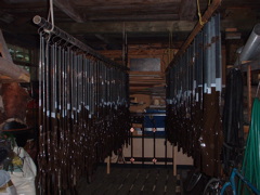
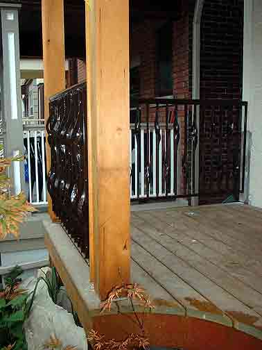
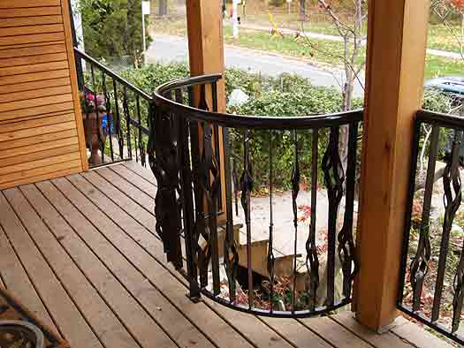
Overall view of the second installation |
Half circle element from the front door |
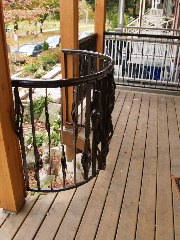
Angle changes around the circle |
 |
 |
 |
Close view showing changes of angle |
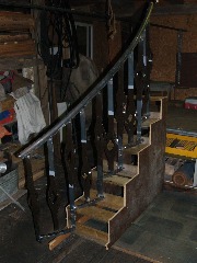
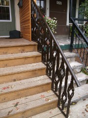
The straight right hand stair rail |
Seen from the bottom landing |
 |
 |
|
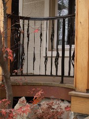
Overall - how it looks from the street |
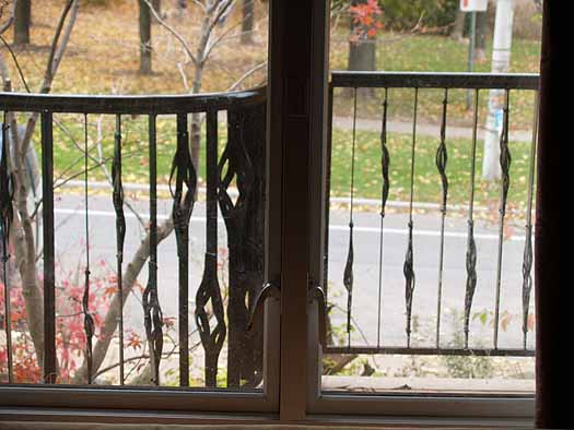
From inside, a clear view of the park |