'Look at all the BONES...'
Addition of Animal bones into a
Bloomery Iron Smelt
June 20, 2020
Wareham, Ontario
Smelt Team:
Neil Peterson, Rey Cogswell
Smelt Master : Darrell Markewitz
ABSTRACT
Several recent papers have suggested the
presence of small fragments of bone sometimes found within the
debris fields related to bloomery iron smelting point to a
possible 'ritual' practice, even so far as proposing a functional
impact on iron bloom quality. How might the physical process
within a complete iron making sequence effect the ability of bone
to endure, and thus remain to be recovered archaeologically? A
typical 'short shaft' furnace will be constructed and operated
through to bloom extraction on a clean working surface. Both bone
pieces and meat containing bone of several animal types will be
added, before, during, at at the final stage of the smelting
process. Afterwards, the debris field will be examined in detail
to determine what remains of the bones.
The BUILD :
The intent of this experiment was to build a standard ’Short Shaft’
furnace, on a prepared clean base, then undertake a careful
examination of the final debris field.
|
|
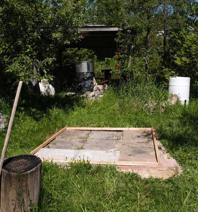
Figure 1 : underlay of
concrete slabs - view to east
|
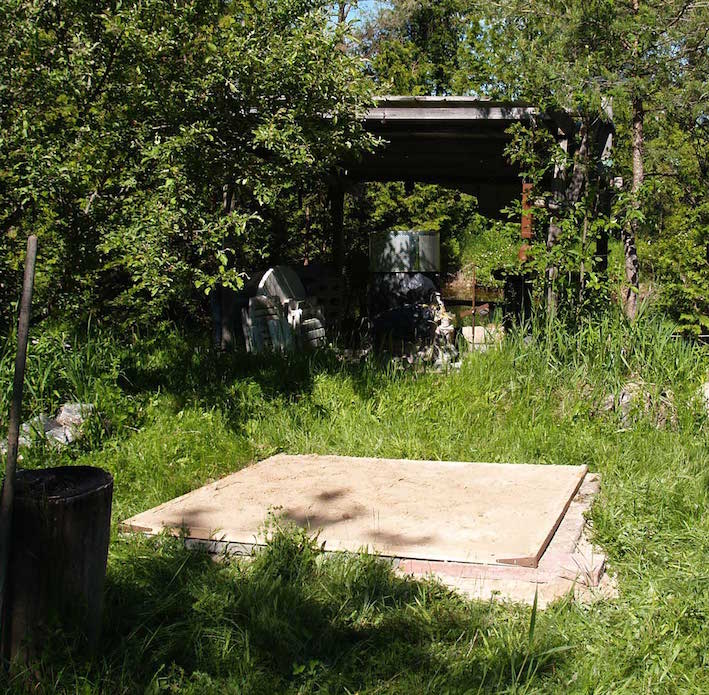
Figure 2 : sand pad |
As this was intended to be a short duration
experiment examined in detail, a hard flat base was created by
laying a set of 24 x 24 inch (60 x 60 cm) concrete patio slabs down
over the natural grass surface of the main smelting area. A square
frame was created from 6 foot long pieces nominal 2 x 2 inch lumber
(so about 4 x 4 cm by 1.8 m). This was used to contain a fill of
course sand, establishing a flat surface with a depth again at 4 cm.
This combination would allow for easy recording of any created
debris, and also in clearing of the area afterwards.
As the function of the furnace itself was not
under investigation, a long proven design and building methods were
used. (1)
The furnace shaft was raised on a plinth of stone blocks, filled
with charcoal fines. This allows for both better control of slag
levels, and assists in the extraction process. There were a
selection of natural granite blocks on hand. (acquired for the
Icelandic Stone Block series, also ongoing at the same time). These
were irregular sizes, but all roughly 10 cm tall, and varied in
width and length. These were laid as one full circle, roughly 30 cm
internal diameter (ID), with a second layer positioned with a gap to
the front (extraction) side.
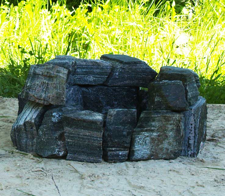 Figure 3 (2) : Stone plinth as established
The mix used for the construction of the furnace
shaft was powdered potters clay (EPK), locally dug course sand and
dry shredded horse manure, combined in rough thirds by volume. This
was hand blended with water to what is considered an ideal
consistency for building.
A metal form at 28 cm wide, wrapped in paper to prevent clay
sticking, was used to establish and control the internal diameter.
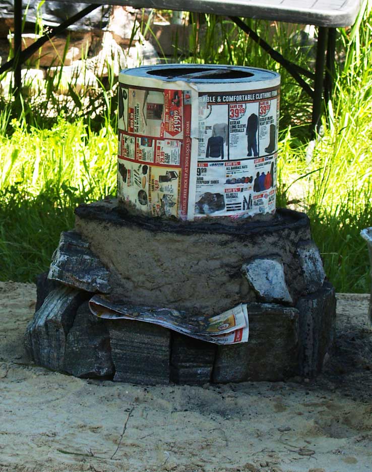 Figure 4 : At the completion of the lower layer, the metal form
in place.
Figure 4 : At the completion of the lower layer, the metal form
in place.
Figure 4 also shows the establishment of a
‘Beardsley Break’, here seen with a coating of charcoal fines. (3)
As is the normal practice, the body of the furnace was built up of
hand sized ‘bricks’ of the clay mix, pressed together and around the
metal form. As a full batch height was finished, the form was pulled
out and clear, with the interior filled with a mix of sand and wood
ash to stabilize and assist drying. As the structure got
higher, it proved necessary to spiral wrap rope around the exterior
to prevent slumping (impressions of the rope can be seen in figure
5).
|
|
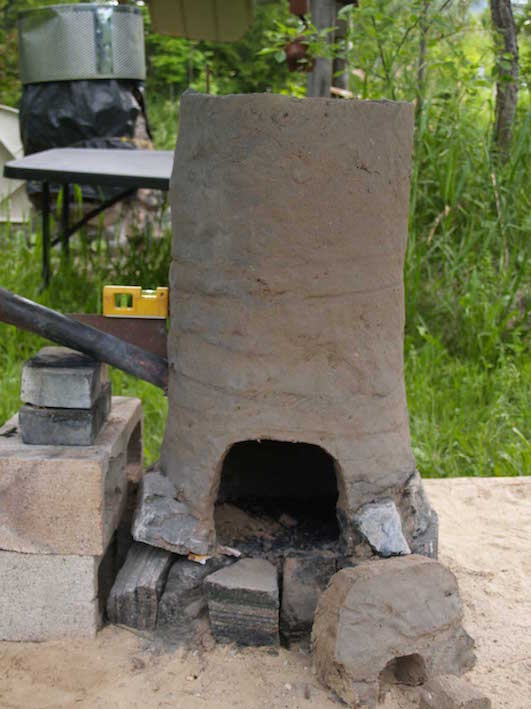
Figure 5 : Finished
furnace, extraction and tapping arches cut,
tuyere installed. |
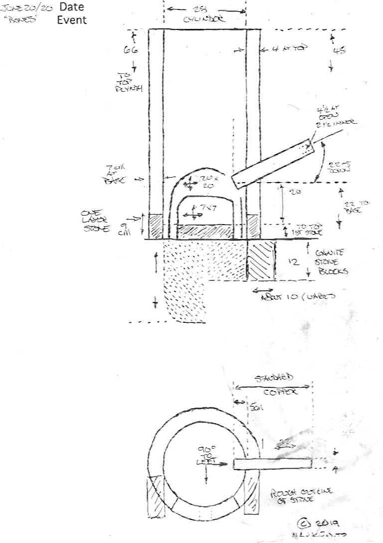
Figure 6 : Overall
measurements |
The extraction arch was cut to almost the height
of the tuyere, total 20 x 20 cm, with a smaller tapping arch on the
lower edge. The forged copper tuyere was set to 22.5 degrees down
angle, 5 cm proud of inner wall, and the base depth adjusted via
charcoal fines to 20 cm. With the total height of the clay walls at
66 cm above the stone plinth, the net result was stack height (above
tuyere) of 48 cm.
A number of concrete blocks were used to support the tuyere and air
system. The placement of these would remain clear within the debris
field during later examination after the completed smelt
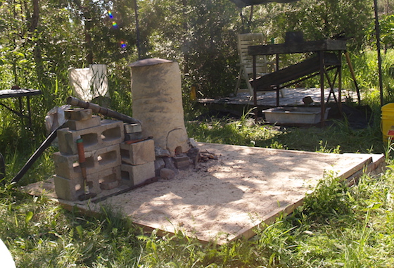
Figure 7 : Overall working area, at the start of the smelt,
view to south east
The SMELT :
The combination of gentle drying fire the day before, plus the
pre-heat sequence also using fine twigs, served to place a layer of
wood ash over the charcoal fines base. Some of the fines had also
been consumed, so the functional base distance was closer to 29 cm
(below centre of tuyere).
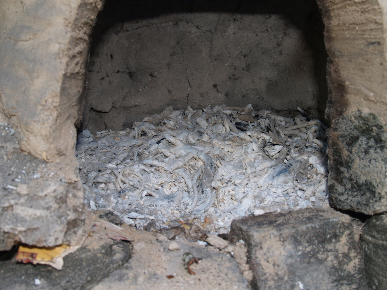
Figure 8 : Ash over charcoal fines, at the
start of the experiment.
The sequence undertaken
for the smelt itself was again fairly standard :
- A quantity of commercial maple charcoal was graded (25 to 5
mm pieces)
- Standard Bucket of charcoal weight at 1.8 kg, a total
of 52 kg was used.
- Air supplied by electric blower, varying from an estimated
650 to 835 litres per minute (4)
- Ore was DD1 analog (red iron oxide) at 53 % Fe, total of 25
kg was used
- Initially charges of iron rich tap slag were added, total of
4 kg.
- At the end a single charge of metallic gromps were added,
total of 1 kg
There was considerable variation in the burn
rates, with outliers at 11 and 23 minutes / bucket.
- Average burn rate was 7.9 minutes per kg
- Average ore addition was 6.7 minutes per kg
- The bloom was (disappointingly) small at 2.6 kg
- The yield was 10. 5 %, with the mass of the gromps included
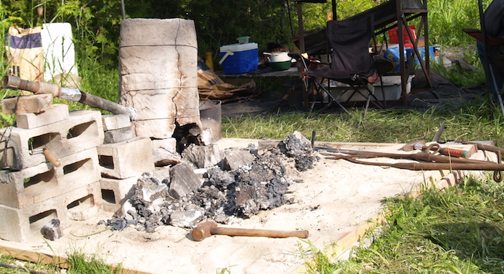 Figure 8 : Working area, the following morning
ADDITIONAL : Photo series over the
progression of the smelt.
Adding BONES :
A quantity of animal bones of various types had
been gathered for addition at various points during the progress of
this iron smelt. Some were retained after household meals, the
pieces with meat on were donated by the local grocery store meat
department (Foodlands, Dundalk ON).
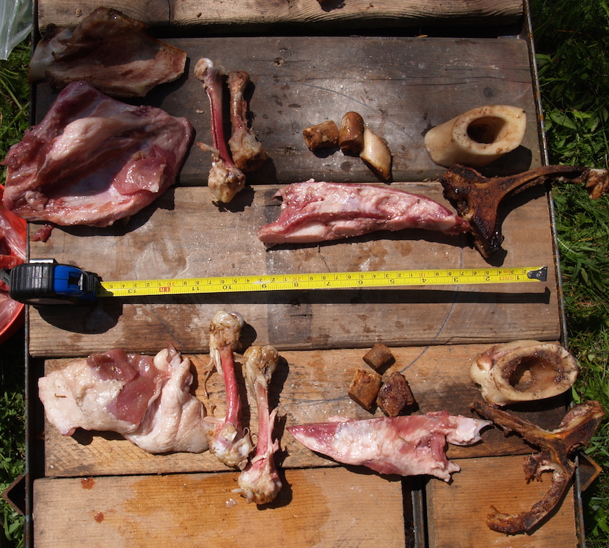
Figure 9 : Bone pieces as collected.
- (far left) = Poultry (Turkey) - breast bone, raw with meat
remaining
- (left) = Poultry (Turkey) - thigh bone, cooked (roasted) with
majority of meat removed
- (right, upper) = Pork - cut rib sections, cooked (slow
cooker) all meat and marrow removed
- (right, lower) = Pork - cut rib sections, raw with meat
remaining
- (far right, upper) = Beef - cut (lower?) leg section, cooked
(boiled) all meat and marrow removed
- (far right, lower) = Beef - cut rib (steak) section, cooked
with majority of meat removed
Although the pieces were photographed against a
scale ‘as fresh’, no other specific measurements were made of sizes
or weights. Because of this, the results should be considered
‘qualitative’. The initial concept was to make two additions,
one at the start of the smelt process and one half way through ore
additions, hence the grouping seen in figure 9.
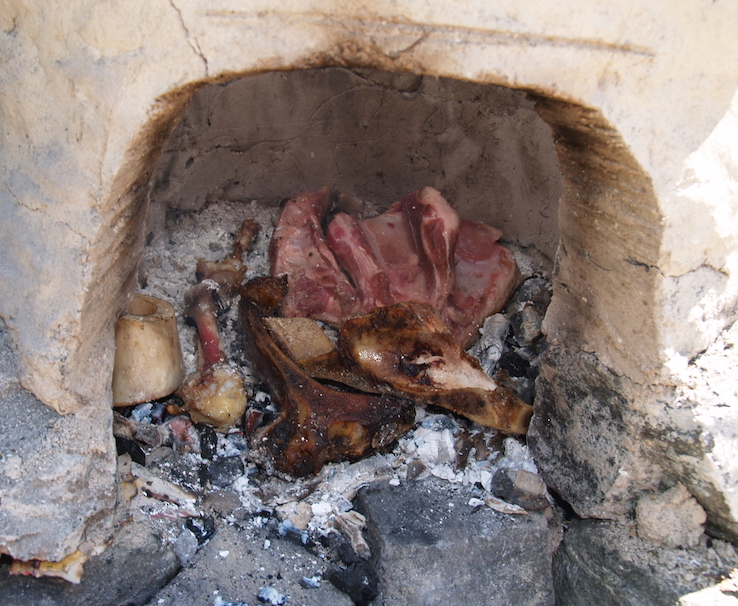
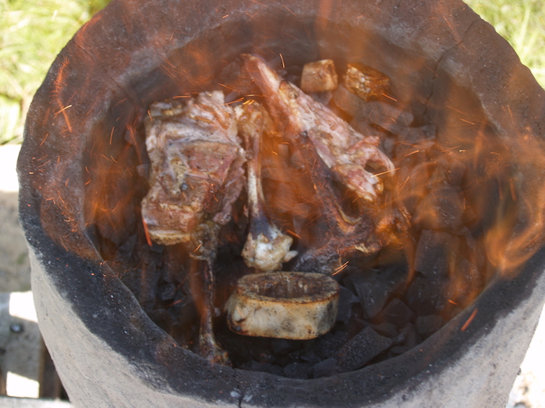
At the end of the preheat phase, the extraction
arch was opened and a set of bones was placed over the hot ash and
still burning charcoal fragments :
Figure 10 : Bones at base level, showing
individual placement. Tuyere is to the left side this image.
- Rear (L - R) : Turkey thigh / Pork ribs (meat) / Turkey
breast (meat)
- Front (L - R) : Beef leg section / Turkey thigh / beef rib
(bracketing) / Pork rib sections
The first pieces of charcoal were carefully added
through the extraction arch, to ensure the few remaining hot pieces
of charcoal would serve to ignite the upper layers. Once it was
clear this had happened, the arch was replaced, and the furnace
filled with rough charcoal. From this point the smelt sequence was
carried out as normal.
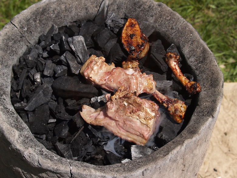
At roughly two hours into the sequence, a second
group of bones was placed on the top of the filled furnace. At this
point (13:40) there had been a total of 5 kg of combined iron slag
and ore added to the furnace (so still early in the iron reduction
process).
Figure 11 : Bones placed part way through the
smelt sequence
- Centre top : Pork rib sections
- Centre : Pork ribs (meat)
- Centre bottom : Turkey breast (meat)
- Left : Turkey thigh
With the decision to make three separate bone
additions, some of the larger pieces (Pork ribs and Turkey breast,
both with meat) were cut in two. The bone pieces added at this time
were placed to one side of the furnace, away from the tuyere. This
was done to echo the normal placement of ore, as the hottest part of
the furnace is directly above the tuyere, typically resulting in
faster consumption to that side (and hence faster dropping down the
stack in this area). The temperature at the top surface of a working
furnace has been measured previously to the range of 400 - 500 C, so
even in the short time it took to grab the camera and record this
image, heat effects are visible (meat cooking, exposed fats starting
to carbonize) (5)
These pieces have been intentionally placed away
from the side of the furnace above the tuyere. The area close
around, especially just above, the tuyere is the hottest part of the
furnace, so charcoal above this is consumed faster. Normal practice
is to place ore in the same location seen with the bone placement,
to ensure the best possible progressing through the lower reduction
zone.
At the end of the ore additions (estimated at
about three hours since the initial charcoal filling), a last set of
bone pieces was placed :
Figure 12 : Bones placed at the end of ore
additions.
- Left top : Turkey breast (meat)
- Left bottom : Turkey thigh
- Centre : Turkey thigh
- Centre bottom : Beef leg section
- Right top : Pork rib sections
- Right centre : Pork rib sections (meat)
- Right bottom : Beef rib section
One extra last full bucket of charcoal was added
to cover these bones, then the charcoal in the stack allowed to burn
down in preparation for extraction.
Another aspect visible in figure 13 are the short
bright orange streaks. These are likely small particles of ore that
have been reduced to fragments of metallic iron, but under the
effect of the air blast are being re-oxidized (burned). This may
even be a sign that the combination of too high a slag bowl and
internally draining liquid slag is resulting in the bloom being
eroded by the blast almost as fast as new metal is being deposited.
(One possible cause of the smaller than expected final bloom size,
which was found to be a fairly
flat ‘cake’, rather than the more typical half bowl shape as
it was extracted.)
Part Two : EXPLORATION
Notes :
1) See : ‘If you
don’t get any IRON…’
2) Images taken during the build suffered in quality because of the
contrast between the bright sunlight and the shadow created by the
temporary overhead cover used at that point.
3) This feature named after George Beardsley, who had
demonstrated it’s use during a cast iron session at the Scottish
Sculpture Workshop in 2014. The purpose is to prevent any
cracking of the clay shaft from extending
upwards, caused when the clay shrinks while formed over an
irregular stone base.
4) Air was controlled by the sliding plate blast gate,
set to marks for 800 / 900 / 100 LpM. More precise measurements
undertaken during experiment
# 90 (October 2021) have been applied here to correct the
original numbers.
5) It is worth noting that despite the high temperatures over the
top of the furnace, the upper charcoal is not showing much effect.
It is usual to see contained water vapourizing (but hard to
photograph). Inside the walls of the furnace at this level there is
no actual free oxygen to support combustion. Air / oxygen injected
at tuyere level has combined with carbon from the charcoal, with
further reaction with the iron oxide ore creating a carbon dioxide
atmosphere at the top of the furnace.
unless
otherwise credited - Text and photography © Darrell
Markewitz