Stacking Up
- on constructing clay furnace walls
Introduction:
There are a number of considerations that go into
the construction of the total shaft (a) height for a direct
process bloomery furnace. This discussion is going to be focused on
small scale builds, with internal diameters in the range of 25 to 30
cm, particularly with prototypes found in Northern Europe, post
Roman to Medieval (so 400 - 1100 AD). These furnaces all had
some kind of human powered forced air, equipment that sets limits on
just how much total air can be delivered, so also how large an
internal volume can be effectively combusted.
Archaeologically, it is rare to find the upper
portion of any furnace, more common are the remains of only lower
walls framing a slag bowl, usually not extending beyond the mounting
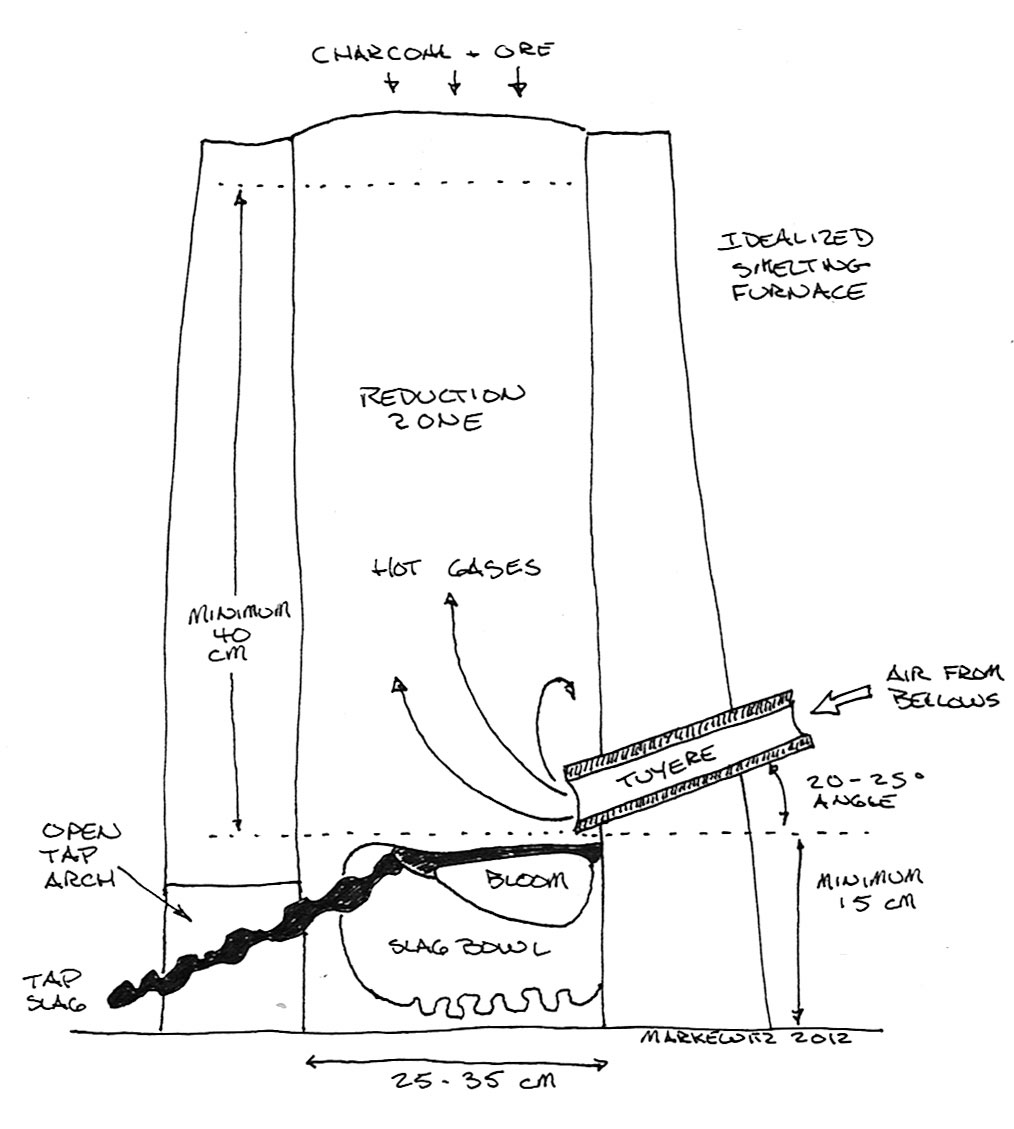
level of the tuyere. There are functional requirements to the
furnace stack (b) height (distance above tuyere) as
demonstrated by extensive experimental smelts, with at least 40 cm
proven a minimum, a measurement of 50 + cm considered ideal.
With the addition of enough space for a functional slag bowl to
allow for the proper collection of the developing iron bloom,
typically 15 - 20 cm, this gives a total furnace shaft height of
such furnaces into the range of 55 - 70 cm. (1)
Diagram of an idealized bloomery furnace
Ideally, a furnace should be constructed to
contain the reactive gasses produced through ignition of charcoal
which are required for the reduction chemistry. (A second
consideration for preventing any side venting is simply making it
possible to work safely around the furnace!) In experimental work,
it has been shown that there are loosely two different ways that a
clay built furnace can survive the kind of operational temperatures
(in the range of 1150 - 1250 + C) necessary. (2)
One format is to use a relatively thin, but
previously fired to ceramic, wall structure. A design developed by Lee
Sauder and Mike McCarthy as the ’Flue Tyle’ teaching
furnace, in this case using a standard chimney flue liner section,
(3) normally a rounded square at about 28 cm ID x 60 cm tall. Here
the wall is composed of a lower fire temperature earthenware at
about 1.5 cm thick, with an additional 1.5 to 2.5 cm clay mixed with
shredded cellulose added to the exterior. With this build, excess
heat radiates off this thin wall structure, keeping the material
from melting during firing. It should be noted that this principle
of construction does not appear in the archaeology however.
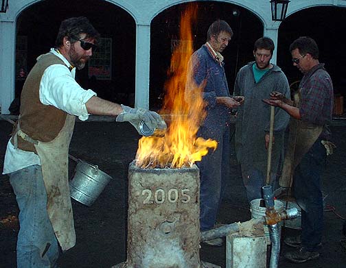
Flue Tyle furnace - Early Iron 2, 2005
Skip Williams feeds, behind (L-R) Jake Keen, Mike
McCarthy, Lee Sauder
Historical furnaces are all built on the ‘make it
thick enough to endure’ principle. Furnaces can be either partially
or fully earth banked, or built free standing. Even those furnaces
completely earth bound still will require some kind of semi durable
liner to hold that earth in place. Loosely grouped, furnaces
(or liners) may be constructed of large stone slabs, stacked stone
blocks (with varying amounts of clay fill), or completely composed
of clay (often with additives). (4)
With stone, the pieces need to be of some igneous
type, again to survive exposure to the operating temperatures
produced. Building with stone slabs can prove difficult, as stone
types and forms are determined by local geography, and also in
terms of acquiring pieces of suitable size against thickness.
Corners and seams may still require some fill, again clay being the
ideal caulking material. (Mitigated by the skill at stone building
of the makers!) One additional problem observed with stone slab
construction is that this tends to create a square or rectangular
cross section. The air blast from a single tuyere within a
rectangular furnace tends to produce a D shaped ignition pattern
(flat side centred on tuyere point). This can become a problem with
low air volume / pressure into larger sized furnaces, where the two
back corners may not be fully able to ignite (5)
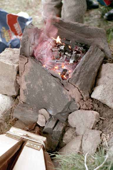
Stone Slab build – Experiment 2, Wareham,
2002
Poor ignition into the rear corners.
Use of ‘stone block’ construction has the
advantage of making for massively thick walls. Effort during
construction is invested against durability over many firing cycles.
Gaps between individual stones must still be sealed, again with clay
the ideal material. This clay will be exposed to less heat damage,
but given the raw volume that may be required, there may not be any
reduction in the total amount of clay required over a self self
supporting clay build. The stone block method of building best suits
a more ‘industrial’ level of repeated iron production.
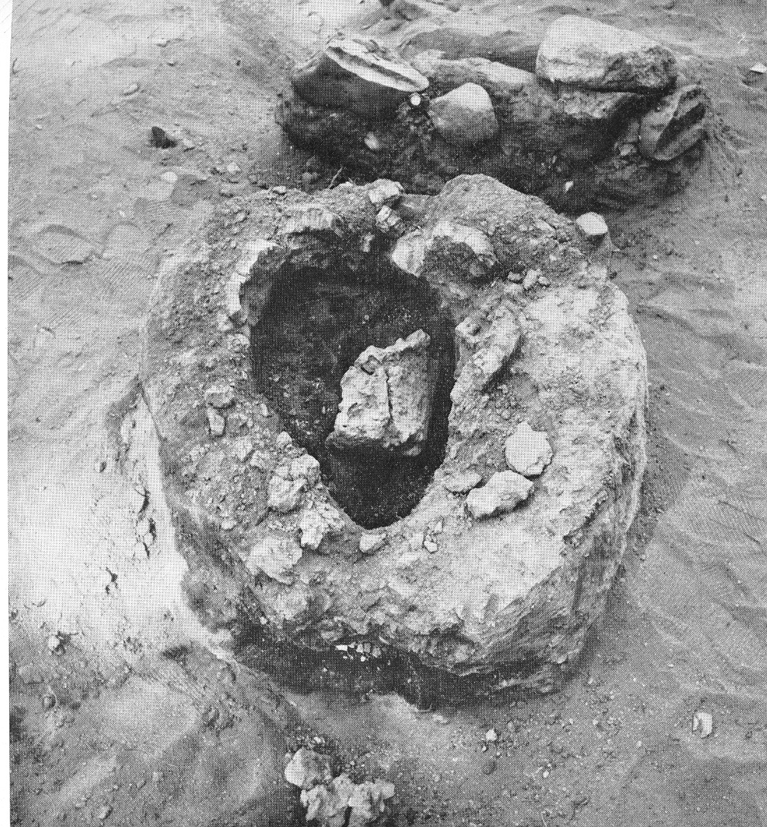
Stone blocks in clay fill, lower base only –
Dalarna, Sweden
Image from I. Serning *
Considering Full Clay Builds :
The final construction material, of greatest
interest here, is the use of clay or clay mixes as the wall
material. There obviously will need to be a consideration of
the qualities of available clay plus modifications possible via
various additives, and how this effects both simple handing and
stability during construction, to the final heat resistance dynamic
of the finished build. Generally it has been the experience over a
large number of working smelts by various teams that a clay wall
thickness of 5 cm is a bare minimum, with 7 - 8 + cm thickness in
the lower sections more practical.
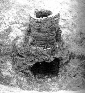
Rare remaining full clay build, 80 cm tall
– Lodenice, Bohemia
Note that the tuyere point (most heat erosion) and
extraction arch are made as a separate, replaceable, wall
section.
Image from R. Pleiner *
Individual natural clay bodies vary enormously
between locations, importantly here in terms of their eventual
melting temperatures. Some clays may melt completely at the
operational ranges of the iron smelting furnace. One simple way to
modify this is to add a volume of ‘sand’ into the mixture. (6)
Generally sand types have higher meting points than clays, so
addition will increase endurance to high temperatures. Sand also
does not absorb water, so higher sand mixes tend to be much more
stable during the initial drying phase of construction, where high
clay compositions can shrink considerably (10 - 15% not uncommon).
Balanced against this increase in refractory quality is that adding
sand makes the starting build mix less ‘sticky’, requiring more care
during the construction. (7)
The DARC team started experimenting with
adding various organic materials to a clay and sand mix quite early
our long series of test smelts, borrowing ideas from both other
practical workers and from examples of the use of clay ‘cobb’ in
constructing things like bread baking ovens and pottery kilns. It
was discovered that chopped straw or hay (available from local farms
around Wareham) could provide good re-enforcement against cracking,
but also created problems with both consistent mixing and in
blending together of individual ‘lumps’ when building walls up.
Generally, walls using mixes including roughly 1/3 by volume chopped
straw proved easiest to construct when these were thicker, in the
range of 7 - 8 cm. With our own builds, inclusion of the larger
diameter pieces of straw were clearly visible after firing. Although
the plant materials burned away well before clay had heated to it’s
sintering temperature, the remaining voids are obvious visually.
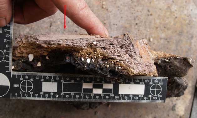
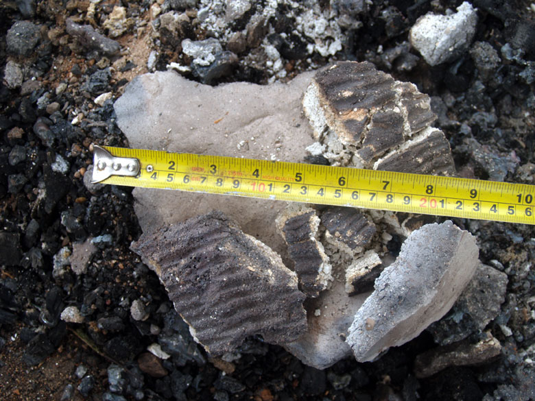
Clay with field grass, detail. Furnace built
June 2006, fired a total of 5 times, then left to naturally
erode.
This image taken June 2021, void lines from burned away
vegetation clearly visible.
Work by Michael Nissen, demonstrated at
the ‘Iron in Thy’ (Denmark) symposium in 2008, suggested the use of
dry, shredded, horse manure as a good organic binder. (8) The first
full furnace build using what has become our standard mix of 1/3 by
volume dry clay, course sand, and (dry!) manure was undertaken here
in May 2012. Although a more subtle effect after a furnace is fired,
inclusion of this material is also visible to the eye.
Clay mixed with course sand (white) and
shredded horse manure, after firing.
#88 - Icelandic 9 (3A), June 2021
Considering Clay Building Methods :
The first full build with clay a the wall
material was in June of 2004. This was a group effort, with a lot of
individuals involved in preparing the components for the mix,
blending these together, then building up the furnace walls. Two
major problems became quickly apparent, maintaining consistency of
the material, and varying skill in the actual build. In attempting
to add more clay to build upwards, the helpful (but unpractised)
hands ended up pushing as much downwards as they blended new
material. The end result, despite the volume of clay used, was a
very short furnace with very thick walls.
Finding the ideal consistency of mixture, here
meaning level of plasticity created by amount of water added to the
dry ingredients, is a continuing problem, even as individual members
of the team have acquired considerable experience gained from
building scores of furnaces over the last two decades. Generally,
those mixtures with higher water content, being softer, are easier
to both physically shape, and to merge successive additions together
into a seamless whole. The balance is that with increased softness,
slumping of the clay as the stack is built upwards also becomes a
significant problem. It is clear that one element is personal taste,
which has been found to also be related to raw physical size and
strength. Neil Peterson, at over six feet and well over 200 lbs, is
happy working with a fairly stiff composition, partially due to
larger hand size, but also because of pure power. Darrell Markewitz,
on the other hand, although only a few inches shorter, weighs in at
only 160 lbs, and finds a much softer mix much easier to manipulate,
substituting considerable experience at hand building for strength.
Controlling wall thickness, solid blending of additions and avoiding
slumping are all skills learned through practice.
In a protracted experimental series such as
developed over the years, building furnaces of a fairly consistent
size, in terms of diameter, height and wall thickness were
considered extremely important. Over many furnace builds, it has
certainly been found that controlling the building of clay forms the
size of bloomery furnaces is another example of ‘it’s harder than it
looks’. Experience is required to know how much pressure downwards
needs to be applied to fuse additional lumps of clay material,
without applying so much force that the lower sections distort
outwards. Skilled hands most certainly can effectively create
uniform profiles at desired thickness, but as is so often the case,
experimental workers can simply lack these skills. It should be
noted that archaeological furnaces most often show distinctive
variations in shape and wall thickness illustrative of free hand
building.
Unskilled work producing distorted shape
over a free hand build.
(Note marks from rope binding - discussed later)
Scottish Crannog Centre, 2016
Considering the Use of Forms :
To this end, the simple solution arrived at was
through the use of standard forms to shape diameters. This has
primarily been through the use of sheet metal formed into cylinders,
or employing pre-existing metal containers. Along the way, some
implications towards possible historic methods have been suggested.
Starting with Experiment #3 (June 2003), a sheet
metal cylinder was used to set the internal diameter of the furnace.
Wall thickness was established with each handful of clay material
added as the stack was built up, and the build process is easily
carried out from all sides. One clear advantage was that it was
possible to control this thickness of each addition by pushing
inwards (towards the form) with one hand as pressure as also applied
downwards with the other to assist in fusing the new handful. After
the full build was complete, typically the furnace would be left
overnight with the form in place to stabilize the structure, and to
allow some evening out of the moisture content between the
individual additions of material. The next day, the metal form had
its edges separated (held in place by several small bolts), then
carefully pulled free and removed. This allowed for more even air
drying from both sides. One important modification to the basic
method quickly became clear - the addition of a couple of layers of
paper on to the metal (taped in place newsprint proving simple and
ideal). This created an effective separation, preventing the clay
from sticking to the metal form, making its removal much
easier.
In an early attempt to speed the build process, a
number of furnaces were constructed using two sheet metal forms,
setting inner and outer diameter (so also wall thickness).
Individual lumps of clay material were then dropped down between the
forms, then tamped in place from above with a wooden tool. Although
this certainly made for a faster build process, it generally was
found that it proved more difficult to ensure the separate additions
were fully blended at the seams. Also the downward force of the
packing tool had a tendency, especially at the earlier stages of the
build, of distorting the two forms into more irregular oval shapes.
This also would result in variations in wall thickness over cross
sections.
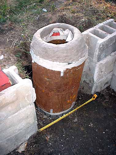
Build using two forms, just before these were
removed.
Experiment #17 - June 2006
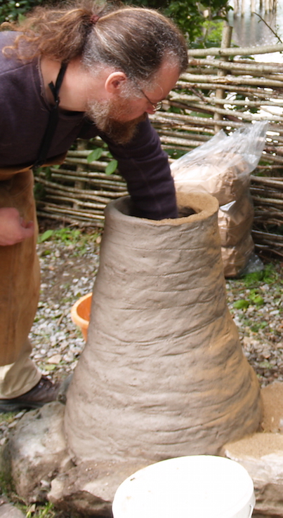
As much as through luck as intent, an ideal metal
form was found, 28 cm in diameter and 40 cm tall, constructed with a
partial end cap that made it more rigid. Although creating a
standardized diameter for test furnaces, use of this form does
require lifting part way through the build sequence. Experience has
shown that typical ‘batch’ of hand mixed clay / sand / manure allows
for building up roughly 25 – 35 cm of wall height, when constructed
to a thickness of between 5 – 8 cm. It has been discovered that
after lifting the metal form clear, the furnace interior can be
re-enforced by filling with a mixture of 50/50 dry sand and wood
ash. This packing also serves to help pull moisture out of the clay
walls. After filling to about 5 cm below the first batch build
height, the form is covered again with newspaper and set on top of
the packing, ready for the next layer.
Dependant on the skill of the workers, and the
plasticity of individual clay mixes, there can be problems with the
lower part of the walls sagging down an outwards as new material is
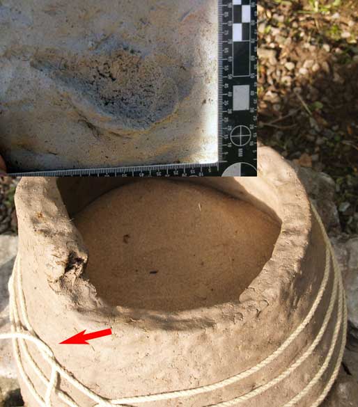
added on top. This can easily be controlled by spiralling rope over
the outside of the walls. The rope will press into the soft
clay, resulting in a clear impression on the outside surface.
Whether or not this would result in an archaeologically recoverable
feature is uncertain. Repeatedly, it has been seen that the outer
layers of clay do not become hot enough, even over a full smelting
cycle, to actually sinter into a ceramic, and thus could be expected
to simply wash away. (9)
Showing the use of (sand) packing and rope to
stabilize a clay build.
The inset is the mark created by tucking under the loose
end of the rope – as done at the indicated point.
Scottish Crannog Centre, 2016
In a strictly Viking Age context, a rigid form
could be created by use of wooden cooperage. To allow the individual
staves to be removed, these could easily be held loosely in place
into circular form by having an exterior binding of rope (in place
of fixed wooden or metal bands). Use of either a straight
sided cylinder or as an ‘upside down bucket’ for conical profile,
would also allow for consistency of interior diameter over multiple
builds which would have advantages at ‘industrial’ iron production
sites (such as Hals). As a wooden surface, intended to be removed,
is going to result in the same kind ‘clay sticking’ problems as we
have experienced, this suggests the possible use of a separation
layer, with cloth, leather or birch bark all possibilities. If
cloth, there is the possibility finding texture patterns on the
eventually sintered clay walls. Sauder regularly uses a method that
echoes this, by taking a number of thin, narrow wooden strips, which
are fixed to a wooden disk at top and bottom. These are burned out
as part of the drying fire later.
An important consideration overall is that our
use of a metal rigid form will only (easily) allow for a cylindrical
profile to the interior of the furnace. There has been found that
there is some advantage to constructing furnaces with an overall
conical shape. (10) Although most easily achieved through (skilled!)
free hand builds, what kind of alternate internal forms might be
employed?
|
|
 |
|
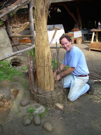
Furnace build using bundled
vegetation as the form.
At Eindhoven, Holland, 2008 (11) *
|
Impressions left on clay walls from
use of an internal wicker frame
(Pictish, 2014 - furnace build illustrated below) |
There is archaeological evidence of the use of
various types of bundled vegetation used to create an internal form.
The example seen above uses river reeds (originally gathered for use
as roof thatching). Cut grasses (crop plants or otherwise) or small,
straight sticks all work as well. Grasses have the advantages of
creating a relatively smooth surface, and also are quite pliable.
With gathered sticks, one potential problem is that clay can be
forced between the gaps, resulting in a rough inner surface to the
furnace. These rough edges can cause the pieces of charcoal to
tumble as they drop downwards as lower levels are consumed. This
rotation can in turn speed the fall of individual ore particles down
the shaft, at least potentially reducing the time for reduction.
(Like any chemical process, the reduction of iron oxide to metallic
iron is not instantaneous.) A potential solution to this
effect would be again to cover the outside of the bundled sticks
with cloth, leather or birch bark. This is likely to produce an
interior surface patterned with random shallow grooves in a wave
like pattern (and again cloth potentially leaving additional texture
impressions).
One clear advantage to the use of bundled
vegetation is the ability of that bundle to flex as the surrounding
clay begins to dry and shrink, most especially the situation with
use of grasses.
Build using a wicker basket internal form,
resulted cracking
Pictish Iron Age Test, June 2014
Use of a rigid form that does not allow for the
shrinking of the drying clay is certainly going to end up causing
major cracking in the body of the furnace. One way to avoid that
problem would be to start a drying fire inside before allowing the
clay any time to significantly air dry, consuming the form material.
There can be other problems associated with this process unless
considerable care is undertaken however, most significantly causing
spalling off of clay fragments because of the explosive expansion of
internal water into steam. (12)
An alternative to an internal form would of
course, use of an exterior one. In actual practice, this proved so
difficult that the idea was abandoned. If the form was the full
height needed for the complete build (so at least 60 cm, possibly
taller), it is not physically possible for a worker to reach down
far enough inside the small space created to effectively apply clay,
at least at the lowest part of the build. (13) It is freely admitted
that there has not been an attempt by this team to employ a shorter
section of metal form, lifting this as the work progresses. How this
might be supported as it was lifted higher would need to be
explored.
A Conclusion :
The nature of clay as initially a plastic
material, transforming to a relatively durable ceramic when exposed
to smelting temperatures, might allow for indications of
building methods to be recovered archaeologically. Generally
however, working furnaces are build out of doors, for obvious fire
control reasons, so used furnaces will be exposed to the full
seasonal variations of rain and temperature. It has been found that
even on multiple firing cycles, the penetration of enough heat to
convert raw clay into a fully sintered ceramic appears to be limited
to roughly 3 to 5 cm. (9) Any wall material to the outer surfaces
quickly washes away as unrecoverable mud. The porous nature of
sintered clays, especially with the use of various temper additives,
combines with exposure to water and the freeze / thaw cycle to
relatively quickly fracture existing walls to small fragments. In
combination any remains are unlikely to fully represent original
wall thickness.
Ancient bloomery iron sites are most likely to be
chosen for their proximity to suitable iron ore, more that any other
single factor. The wide assortment of build materials and styles
employed historically, even within the same cultural group, suggests
a kind of ‘make with what we’ve got’ principle being applied to
furnace construction. Conservation of clay materials is not
considered to be a major concern to ancient builders, as natural
clay deposits, if accessible at all, tend to exist at large volumes.
Use of a form will speed builds, and perhaps most importantly allow
for standardized shapes and diameters. All of these factors would be
desirable for historic iron processing sites where a repeated
production series was undertaken (what has been termed ‘industrial’
level sites).
One very important result of the use of a form is that the support
provided allows for effective construction of much thinner walls
than is possible over free hand building. This may be significant
when considering builds that use a clay liner with earth or turf /
sod construction (again, such as seen at Hals).
* Note : The images used of archaeological furnaces are used
without expressed permission, original source indicated. All other
images by the Author.
Definitions:
a) SHAFT : Here meaning the total height of the furnace interior,
from hard ground surface to top edge.
b) STACK : Here meaning the distance from the centre of the tuyere
to the top of the furnace, which includes the major combustion and
reduction areas. This will be less than the total shaft measurement.
Notes:
1) For a general description of a basic bloomery iron smelting
method, see : 'But If You Don't Get Any IRON...' Towards an
Effective Method for Small Iron Smelting Furnaces, the EXARC
Journal issue 2012/1
http://www.warehamforge.ca/ironsmelting/Get-Iron.pdf
2) A complete description of the overall process and theoretical
conditions inside a bloomery furnace can be found in : Iron in
Archaeology, The European Bloomery Smelters, Padomir Pleiner,
2000 : pages 133 -136
3) A practical guide to building and operating the Flue Tyle furnace
by Skip Williams is available :
http://www.warehamforge.ca/ironsmelting/FlueTyle/index.html
4) This frame of reference is specifically the one of study and
experimental test here. ‘Roman’ furnaces are generally described as
much larger diameters and specifically significantly taller stacks.
With furnace heights over 170 cm (+/-) a natural draft is created,
enough to provide the operating temperatures for effective
reduction. The introduction of water powered systems, starting in
roughly the 800’s and spreading through most of Europe by about 1100
+, allows for much larger furnaces, producing more massive blooms.
5) This has proved the pattern on our earliest tests, where stone
slab furnaces were used. One possibility might be to place the
tuyere not in the centre of one side, but to the corner of the
furnace. This might also help with some of the fitting problems of
providing for the hole needed for the tuyere itself. (Note that this
concept has not been tested by this team)
http://darkcompany.ca/iron/iron0502/index.php?submenu=I
6) ’Sand’ is a bit of a problematic term, as it actually refers to
the particle size, not the mineral composition itself.
Here in Ontario, our locally available sand is finely ground and
water deposited granite, with a high silica content at roughly 70%.
As this discussion is (eventually) aimed at the ongoing experimental
work to the Viking Age Icelandic furnaces excavated at Hals, it
should be noted that any sand available there would have been basalt
source, with a silica content at roughly 50%.
7) Lee Sauder uses a clay with sand mix in the construction of his
furnaces. For an excellent overview and guide to practical bloomery
smelting technique, see his paper : Practical Bloomery Smelting,
(for Materials Research Society) 2001 : https://s3.amazonaws.com/images.icompendium.com/sites/eliz2406/sup/3694985-Practical-Bloomery-Smelting.pdf
8) A (very) brief overview of Michael Nissen’s work (in English) can
be found :
https://ribevikingecenter.dk/en/learn-more/extraction-of-iron.aspx
9) A fuller discussion of both heat penetration effects and
especially furnace erosion over time can be found in : Evidence
of Absence -
Erosion of Bloomery Furnaces, May 2021 :
http://www.warehamforge.ca/ironsmelting/erosion/erosion2021.html
10) As developed by Sauder (with others at his ‘Smeltfest’
workshops), dimensions such that the top opening diameter is equal
to a measurement that matches the placement of the tip of the
tuyere. For an insert tuyere, this point is typically 5 cm beyond
the interior furnace wall. The overall profile becomes a conical
section, the base wider than the top. This can be symmetrical, or
with the rear wall (opposite the tuyere) set horizontal. Both those
shapes are seen in historic furnaces, along with cylindrical builds.
11) Smelting Enriched Bog Ore in a Low Shaft Bloomery,
Johnathan Thorton, 2008. Image from a report on the 3rd
International Symposium on Early Iron, held at Eindhoven, Holland :
http://iron.wlu.edu/reports/Eindhoven%20Smelt%20Report.htm
(note that this image used without expressed permission)
12) This exact problem occurred with Experiment #26 (October 2007)
where prepared commercial clay was cut into brick like slabs to
construct the furnace walls. Despite a 90 minute pre-heat sequence,
steam explosions blew off several pieces of clay (the size of golf
balls, flying 3 – 5 metres!):
http://www.warehamforge.ca/ironsmelting/icelandicA/index.html
13) Using myself as an example, at 175 cm and admittedly fairly long
arms in proportion. My own ‘armpit to first knuckle’ length is 64
cm. This would just barely allow me to reach down inside to possibly
apply clay to the bottom most layer. The working space diameter
would be roughly 45 cm (assuming 7.5 cm wall thickness and 30 cm
ID). Normally two hands are used when applying additional clay
however, one pushing fresh material down and the other to brace
sideways to the existing layer. With my own shoulder width at 50 cm,
I simply can not position both working hands correctly down the
bottom of such a metal tube.
Unless otherwise credited
Images and Text ©
2021 Darrell Markewitz