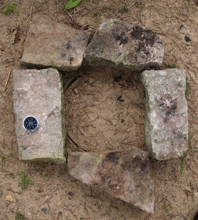
Limestone blocks laid out for the plinth
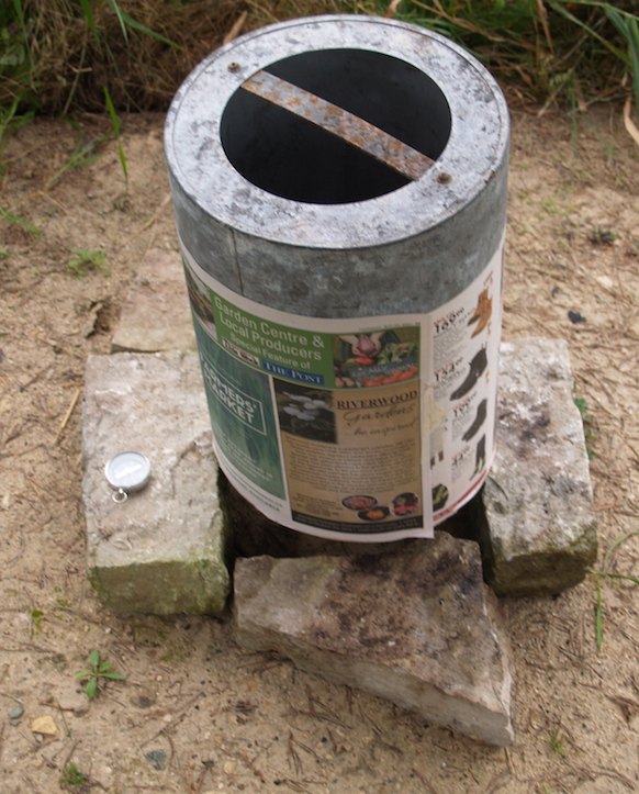
Setting the metal form (note cover of newsprint!)
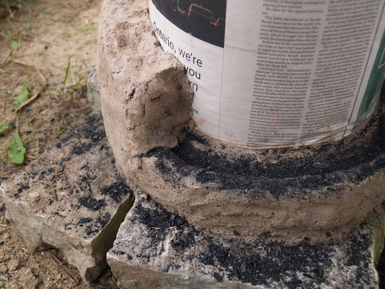
Early in the build, showing the ‘Beardsley Break’.
Wind & Weathering :
air delivery & long term
erosion
Darrell Markewitz, with contributions by Neil
Peterson
For the last bloomery iron smelt of the 2021 season, a standard
pattern furnace was constructed, then fired using a typical
sequence. There were two primary goals to this experiment :
Wind - The recent acquisition of a high quality air flow
meter allowed for precise and frequent measurements of the actual
'in line' delivery of air into the working furnace. A by-pass
system allowed for the shifting to human powered bellows at a
number of points, also with accurate recording of volumes
produced.
Weathering - A new furnace was constructed on a clean sand
pad, set to one side of the main smelting area. Photographic and
video recordings were made of the extraction sequence. The remains
of the furnace and the resulting debris field will be exposed to
weather, and the aging documented as the features erode. The
intent is to continue these observations over the next ten years.
This version, prepared for the web site documentation, has
additional images
Part One - The Smelt :
The furnace constructed for these experiments was the long proven
’Short Shaft’ type. (1) In this case the furnace structure was
placed on a rectangular plinth formed from fairly uniform
thickness limestone blocks. The clay walls were constructed of EPK
powdered clay, course sand, and dry shredded horse manure, rough
thirds by volume, again a standard mixture. Individual fist sized
‘bricks’ were placed against an internal metal form. To reduce the
possibility of cracks generated from clay shrinking against these
stones, a ‘Beardsley Break’ was incorporated at the top of the
first line of clay. (2)
|
|
|
| Figure 1
: Limestone blocks laid out for the plinth |
Figure 2 : Setting the metal form (note cover of newsprint!) |
Figure 3 : Early in the build, showing the ‘Beardsley Break’. |
The initial construction would result in walls built to 65 cm
height. On later consideration, It was decided to add a further 10
plus cm (to a total of 77 cm). That initial build would have
allowed for roughly 50 cm of working stack, considered effective.
It became obvious in the days leading up to the smelt however,
that participants were going to be limited (only Markewitz and
Peterson had confirmed). Adding the extra height would provide a
bit of additional working time, so ensuring no interference with
the reduction of ore.
One factor that may have had significant impact on the later durability of the construction was that the builder (Markewitz, working alone) had experienced significant nerve damage to the left hand and was still recovering, and so did not have full strength to apply.
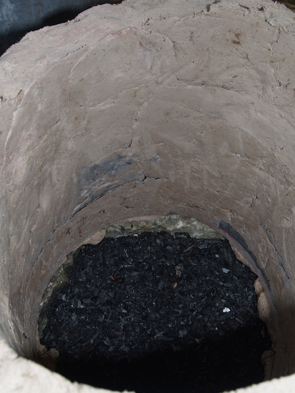
Figure 4 : Furnace interior after the first layer completed,
showing minor breaks on inner surface
 |
 |
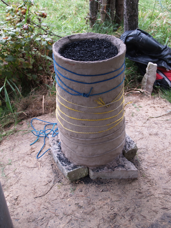
| Figure 5 : Completed furnace after initial build, with rope spiralled over exterior, interior packing |
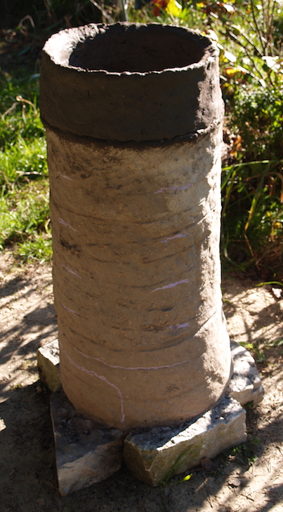
Figure 6 : After addition the upper ring
|
 |
 |
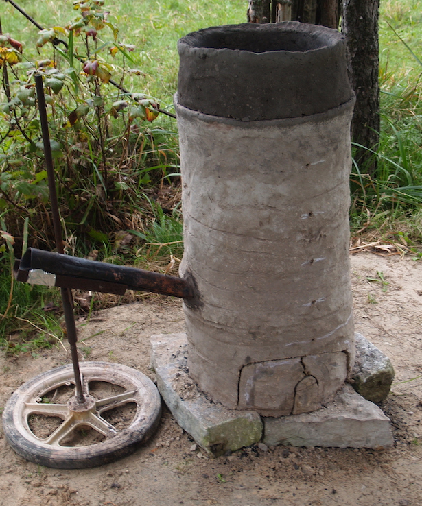
| Figure 7 : With tuyere installed, arches cut |
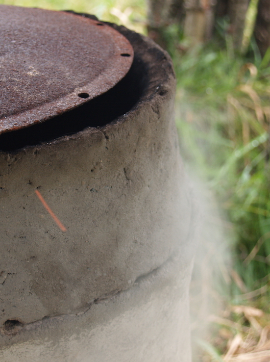
Figure 8 : Moisture venting off the clay surface during drying fire |
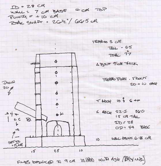
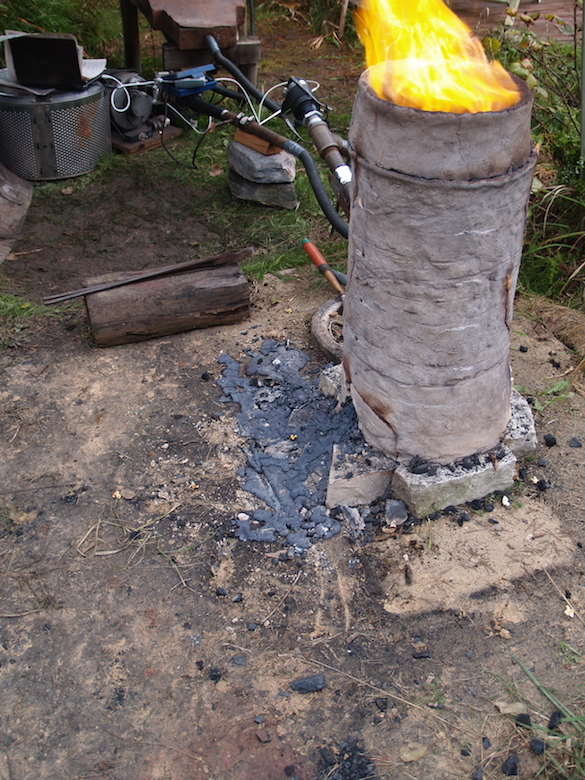
Figure 10 : Overall view of the working area during the pre-heat,
with the furnace on the sand pad, the air supply systems to the
rear.
Darrell Markewitz was smelt master, with Neil Peterson as lead
hand and record keeping, Richard Schweitzer assisting on
bellows.
Over the smelting sequence a number of measurements of internal
temperatures were made, using an OMEGA HH12B digital meter.
Measurements were taken by using a number of different
thermocouple types, inserted through the holes cut into the body
of the furnace. Each was pushed through to about 2 cm beyond the
interior wall. A number of physical problems hampered the use of
these probes. There were a good number of fine wire thermocouples
available, but these were rated to only 1100 C, and did fail into
the higher interior temperatures that were reached. (4) There was
also one rigid metal shielded probe, rated to 1330 C.
Unfortunately, the holes prepared were just barely larger that the
shaft, and so once clay expanded due to heating and slag
accumulated, it proved impossible to insert that probe through the
furnace walls.
| TIME | 1352 | 1402 | 1430 | 1439 | 1521 | 1530 |
| ARCH 20 | 1170 | 1135 | 1210 | |||
| 30 | 930 | 1040 | 1190 | |||
| 40 | 780 | 840 | 1190 | |||
| 50 | 550 | 800 | 1000 | |||
| 60 | 320 | 650 | 905 | |||
| 70 | 250 | 460 | 715 | |||
| TUYERE 20 | 1180 | 1180 | 1315 | |||
| 30 | 1030 | 1030 | 1350 | |||
| 40 | 1190 | 1190 | O/L | |||
| 50 | 800 | 800 | - | |||
| 60 | 780 | 780 | - | |||
| 70 | 610 | 610 | - |
Table A : Charting the interior temperatures
Distances above furnace base in cm
O/L indicates problems with the meter, no further
measurements possible
As was fully expected, there would be a number of slag taps over
the course of the full sequence. The first two of these were based
on observations (sound and visual) of rising slag levels
potentially interfering with air flow. As the first of these were
very early into the addition of ore, the first at 6.5 kg
(potentially only 2 - 3 kg fallen to bowl level), it was felt the
most likely origin of that stag was from interior erosion of the
furnace walls around the tuyere. Both of these taps were
controlled to small volumes, attempting to drop the interior slag
bowl and level of liquid slag, but to retain as much of a
‘working’ system as possible.
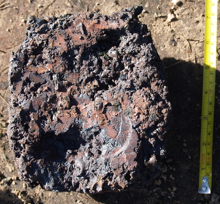
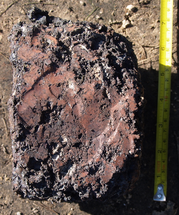
In the later stages of the smelt, there would be two much larger
volume ‘self taps’. For both of those events, the hot slag was
allowed to flow undirected, and initially remain where it
solidified
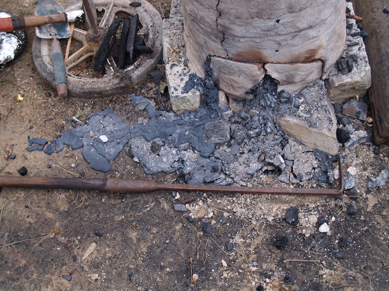 |
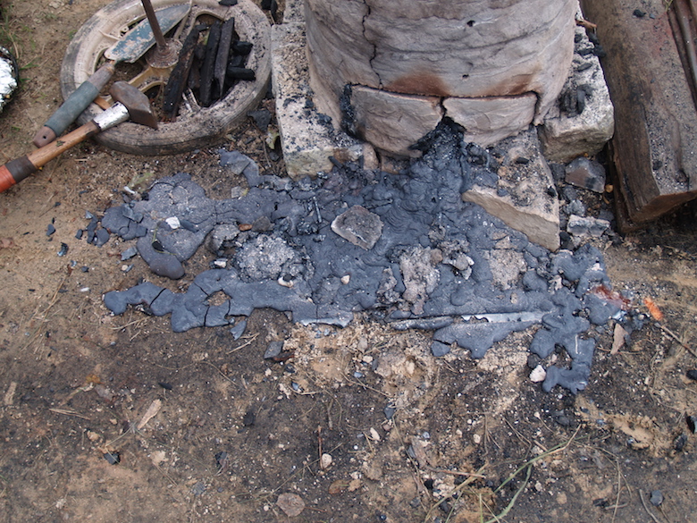 |
| Figure 11 : The results of self tap 1 | Figure 12 : The results of self tap 2 |
Over the course of the smelt sequence there would be three
intervals where a human powered ’smelter bellows’ replaced the air
blast from an electric blower. (Details on this seen in Part 2 : Wind)
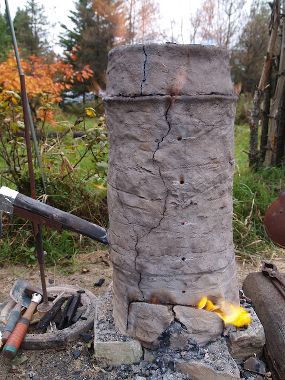
During the course of the smelt, it became clear that the fusing of
the individual clay additions during construction was less
effective than normal. At least two major cracks, running top to
bottom, had developed. This could be attributed to the building
process, as the cracks clearly jogged back and forth along joints
of the individual ‘bricks’. There was also a clear break between
the original shaft and the second additional ring, although this
was fully expected. During the actual smelt sequence, these
cracks, although clearly visible, were not considered a major
structural problem, as there were no actual gaps large enough to
vent furnace gasses visible. In retrospect, wrapping the furnace
with several loops of iron wire should have been undertaken to
strengthen the furnace.
 |
 |
| Figure 13 : Cracking above the front arch |
Figure 14 : At the start of the burn down phase, accumulated tap slag at the front. |
To record the actual extraction phase, two different video systems
were fixed in place, with two different viewing angles. Peterson
undertook the extraction, with Richard Schweitzer utilizing the
‘thumper’ and hammer compacting, Darrell Markewitz provided
general assistance and hammer compacting.
(Peterson seen in blue, Schweitzer in silver, Markewitz in
grey) (5)
 |
 |
Unless otherwise indicated :
All text and photographs © Darrell Markewitz,
the Wareham Forge.