Working towards an Icelandic Viking
Age Smelt
Based on the remains at Hals
Prepared with the assistance of Kevin Smith & Neil Peterson
Introduction:
Kevin Smith (Haffenreffer Museum of Anthropology at Brown
University ), Neil Peterson and I have been discussing the
work Kevin has been doing excavating a Viking Age iron smelting site at Hals
in Iceland. The site is an 'industrial' one, composed of a large number of smelters
that were operated from roughly 875 - 950 AD. The details can be found in 'Ore,
Fire, Hammer, Sickle: Iron Production in Viking Age and Early Medieval Iceland'
(Smith, 2005). In any consideration of this evidence, it must be remembered
that the site has only been partially excavated an the remains not examined
in close detail at this point in time.
The long range plan is for our team to work towards a full historic reconstruction
smelt using the Hals excavations as the model.
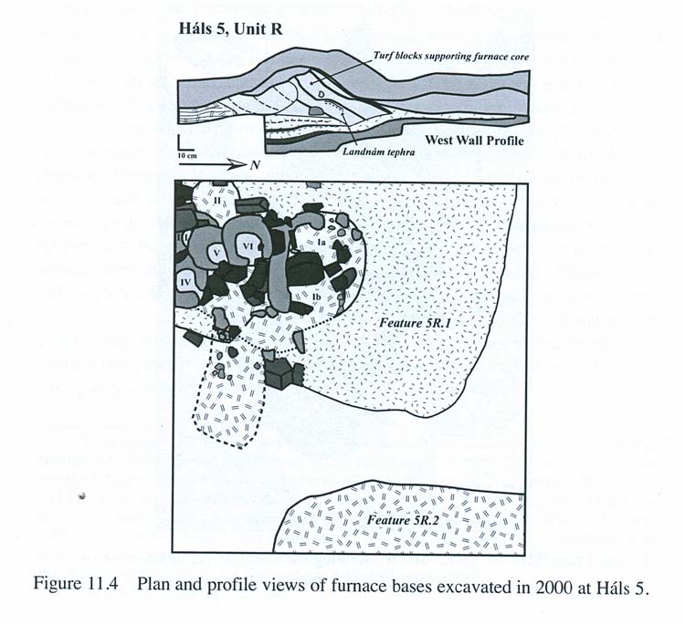
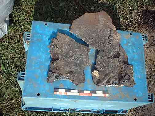
Archaeological remains at Hals (Smith, 2005)
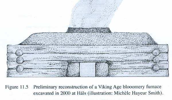
The initial suggested reconstruction (Smith, 2005)
In brief the evidence suggests the following details (letters expanded upon
in the next section):
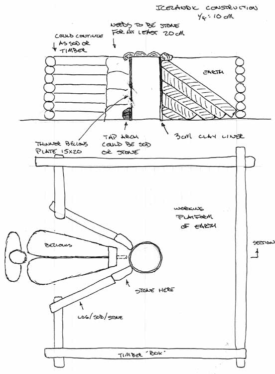
- Basic construction was a conical stack of cut grass sod strips contained in
a box frame of timber.
- Overall dimensions are roughly 2 x 2 m by 1 m tall.
- The most likely working height for the smelter shaft is in a range from 70
to 95 cm total (A)
- The space between the cone and the box is back filled with earth to create
a working platform.
-The shaft of the furnace is cut down into the centre of the sods with a diameter
ranging from 25 - 35 cm (B),
- This shaft is then lined with a relatively thin (C) layer of clay like material
(D).
- A working area at the front of the furnace would either be a tunnel or a slot
(E) cut into the overall frame.
- The tuyere area may have been reinforced, or entirely made up of, stone (F)
- In addition, a separate 'bellows plate' (G) may have been employed
- A 'blow hole' method appears to have been used to introduce the air (H).
- The overall furnace layout and remains of slag bowls both strongly suggest
a top extraction method. (I)
- Originally a primary bog iron ore was used, but its exact chemical composition
is yet to be determined (J)
- The furnaces were charcoal fired, with a large charcoal pit uncovered on the
site showing repeated uses
- The blooms produced (indicated by depressions in slag bowls) were most likely
in the size range of 10 x 15 to 15 x 15 cm (very rough estimate : about 5 -
7 kg )
One proposed layout for the furnaces at Hals based on the remains.
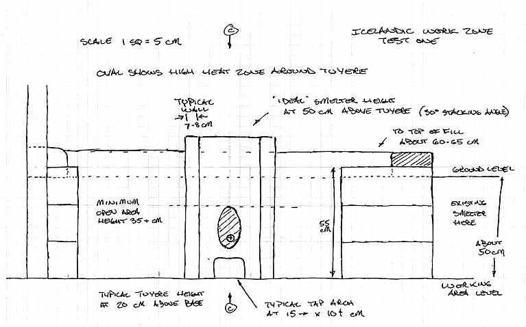
Working from Archaeology to an Effective Smelter:
Determining the working size of the Hals furnace
A) Our own experience has indicated some minimum values for effective smelting:
1) Distance of tuyere above base > 15 cm
2) Height of stack above tuyere > 40 cm.
Past experimental smelts have shown that our 'ideal' furnace layout is for 20
cm below the tuyere (to allow for formation of the slag bowl and easy tapping)
and 50 - 60 cm above the tuyere for the working stack. At stack heights less
than 40 cm, there is simply not enough reaction distance for the chemical and
physical process. (It is noted that both the exact composition of a specific
ore and also the nature of the air supply can effect these stated measurements.)
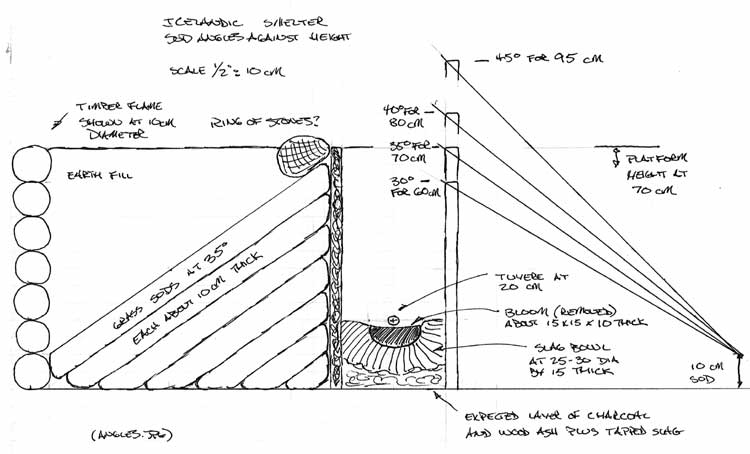
The archaeology shows the stack of grass sods extending roughly 1 m to each
side of the furnace shaft, with the current angle of these sods at roughly 30
degrees. Extending that angle for a 30 cm diameter shaft within a 2 x 2 m framework
produces a total stack height of 60 cm.
It is more likely however that the position of the sods has slumped slightly
over the centuries from their original position. Using a 35 degree angle the
resulting measurements (as calculated) easily allows for a total stack height
closer to 70 cm, or 50 cm above the tuyere (with a 20 cm base distance).
Extending a possible stack angle to 40 degrees, the total stack height extends
to 80 cm, or about 60 cm above the tuyere.
We have found in past experiments that at stack heights over 60 cm above the
tuyere there can be an increasing problem with excess absorption of carbon into
the metal. Extending the sod angles to 45 degrees increases the potential stack
total to 95 cm, or 75 cm above the tuyere point. In light of the potential problems
this would create, both in difficulty in construction and smelt carbon control,
this extra height is not considered likely.
For the reasons detailed, it is suggested that the original construction would
have used a stack angle for the grass sods of between 35 to 40 degrees. With
an interior dimension of the shaft at 25 cm, these stack height estimates would
increase slightly.
B) This working diameter is indicated by the diameter of the slag bowls found.
Our own experience has centred around furnaces in this range, typically 25 -
30 cm diameter.It should also be remembered that both the air system employed
and the dynamics of whatever bellows was used can seriously impact on how effectively
a furnace of a given diameter may perform . (see G below). The larger 35 cm
diameter indicated may present significant problems in generating the required
air volumes. Sauder & Williams have determined that the air volume required
for a successful smelt is roughly 1.2 - 1.5 litres per minute for each square
centimeter of the shaft at tuyere level. ("A Practical Treatise on the
Smelting and Smithing of Bloomery Iron" - 2002) Our own experiments have
confirmed this requirement.
C) A wall thickness of approximately 3 cm has been suggested by remains of furnace
wall. Unfortunately these remains are fragmentary (from centuries of freezing
and thawing).
The construction style at Hals uses the sod to give the support to the structure,
so the clay is operating primarily as a fire proof layer. There will be some
minimum thickness required to balance the erosion effect of the high smelting
temperatures (in the range of 1300 + C). Our experience has shown that thin
walled structures will radiate off excess heat to balance erosion effects. In
this case however, the enclosing sod structure will not allow accumulated heat
to radiate, so erosion may prove a significant factor.
The fact that the furnace shafts are cylindrical also strongly indicates the use
of a clay liner. If the locally available stone was used for creating the fire
proof layer, the resulting furnaces would have square shafts. There would also
remain considerable amounts of large stone pieces with heat damage, slag layers
and significant erosion effects. The resultant slag bowls would also exhibit distinctive
shapes, most likely a D shape overall.
All
stone furnace, near end of main smelt sequence
Stone slab placed just above tuyere showing heat effects after single smelt
event
D) The exact composition of the wall material is unknown at this point. (see
also C above.) Smith has discovered that true clay is available locally as deposits
within certain hot springs. (This clay was tested by Michelle Smith and found
to fire to a hard porcelain like texture.) At this point the original wall material
from the site has not been analyzed in detail. It is thus unknown what, if any,
organic materials may have been added to the base clay.
Our own experience certainly has shown the utility of adding chopped straw to
the clay used for the thicker walled furnaces (7 - 10 cm). With this mixture,
when the clay is initially heated, the steam generated (from working with wet
clay) vents both into and through the hollow straw, reducing cracking (even
preventing steam explosions!). During the main smelt sequence, the straw acts
as a structural element on the outer surface, holding together the walls against
cracks. On the inner surface, where high temperatures sinter the clay, the straw
burns away, leaving air passages that both insulate and spread heat.
For thinner sections, I have been guided by the work of Michael Nissen (Ribe
Viking Centre) and tests with Skip Williams and Jake Keen. Mixing dried horse
manure with the clay greatly improves its heat resistance, but leaves a much
finer texture. Nissen constructs the heavy walls of his earth banked smelters
of this mixture with good results. This material is far less porous than straw
cobb and thus likely more durable under the freezing and thawing cycle (although
this has not been field tested).
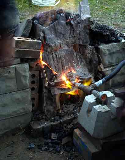
Close up of straw cobb wall (just above bellows plate) after the October 2008
experimental smelt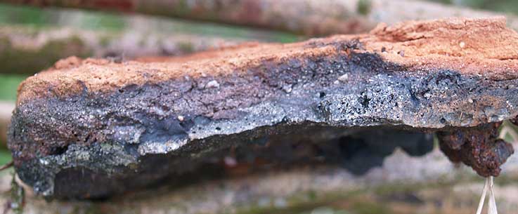
Close up of horse manure mixture bellows plate after smelt by M. Nissen. (thickness
about 2 cm)
E) The first reconstruction drawing by Smith had suggested a wedge shaped tunnel
leading from the exterior frame to the surface of the furnace wall. The DARC
team considers this quite unlikely for a number of reasons. Our own practical
experience leads us to conclude that a triangular slot would be used, open at
the top:
- There is considerable heat vented from the tuyere / tap arch segment of the
furnace wall. This precludes the use of wood as a roofing material for a tunnel.
- The size and required position of a bellows requires more operating space
than can be provided from a tunnel construction. (see details E below)
- Any manipulation of the developing slag bowl (tapping) or clearing obstructions
from the air intake would be extremely difficult, if not impossible, if forced
to work down the end of a long narrow tunnel.
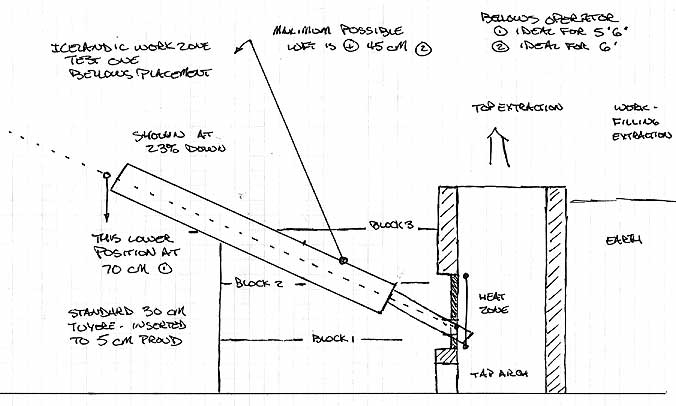
Showing the approximate placement
for a working bellows
There are a number of suppositions involved in the working layout seen above:
1) The raw size of the bellows is based on a theoretical construction that allows
for high volume air production. (More information covering this reconstruction
can be found as part of the discussion on 'Hammered Out Bits', specifically
"Bellows Reconstruction 3")
Our own tests of a bellows unit of the size indicated suggest it should easily
produce consistent air volumes in the range of 600 - 750 LpM.
2) With the bellows set in line to its air output tube, itself set to our normal
23 degrees down (an effective value determined by repeated experiments), the
working end is raised to a height that is perfectly comfortable for an operator
of average stature when standing.
What this arrangement does not account for is how the bellows is actually supported
in the correct position. The simplest solution would be to mount the bellows
on a heavy frame, which is how we have tackled the requirement in the past.
The use of such a frame creates a problem in that it greatly restricts access
to the tap arch. One solution would be to use horizontal timbers attached to
the larger wooden frame around the smelter to support the bellows.
It is noted that it might have been possible to use some form of piping to channel
air to the furnace from a more remotely situated bellows. Heavy leather or hollowed
out branches would certainly work for this, and yet at the same time leave no
traces behind.
F) Although the working portion of the structure could be framed with large
stone slabs, the archaeology does not fully support this. There were a line
of roughly 10 x 15 x 3 -5 cm thick stones found in a V leading towards the location
of the tap arch / tuyere combination (Furnace 6, the uppermost and last in the
series). These stones are a bit on the small size to support a roofed over construction,
especially since much larger slabs are easily available close to the site. (It
should be noted that to date no large slabs have been recovered at the site.
Stones tend to fragments, with the largest about 15 x 25 x 15 cm.) A simple
grass sod wall would certainly work effectively to support the walls and be
suitably fire resistant.
The upper section of the front smelter wall could be made of a single large
stone slab if suitable clay was not available.
Although a suitable sized stone could have been used to support and plug the
tap arch, experiments have shown that a cut block of grass sod (laid upside
down) also works quite well.
G & H) The evidence for the air system used is negative, with no remains
of insert style tuyeres having been found. Slag covered ceramic tuyere tips,
a durable feature at many furnace sites, have not been found at Hals. If forged
iron tubes were used, these leave a very distinctive combination of frozen slag
and deeply oxidized iron after use. Again no remains of this type have been
found. A remote third possibility is the use of bronze or copper pipes. Combined
with thin walled construction at the entry point of the tuyere, tubes made of
this material have proven extremely durable. It would be expected that some
erosion of the tips would occur, which would leave evidence as small melted
balls of metal inside the slag blocks. (In all cases it is noted that these
are still early days in the excavation.)
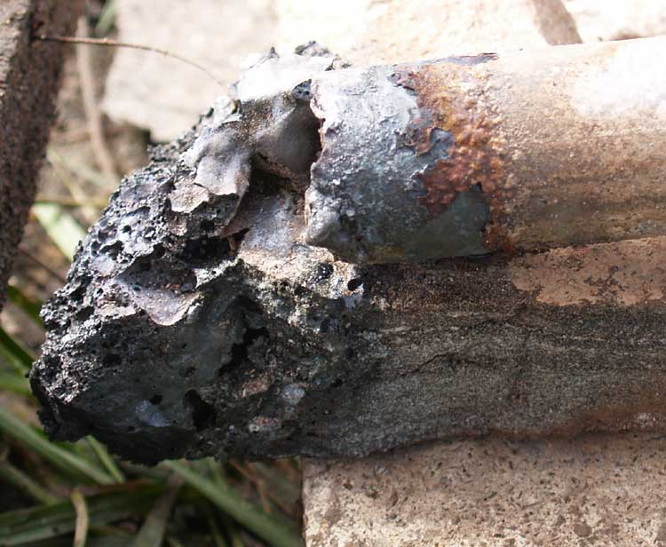
Remains of a steel pipe tuyere after
a single smelting operation
The underlaying principle behind the use of a bellows plate relates to the heat
distribution within a working smelter. A zone of extreme temperature will be
created in a rough oval located around the air inlet. Typically this zone extends
from 1/3 bellow to 2/3 above the air inlet, and symmetrical side to side. For
smelters in the size range and with air flows as under consideration here, that
oval extends roughly 15 side to side and 20 cm top to bottom. A thinner plate
inset to the inner surface of the smelter will disappate heat rapidly enough
to balance the heat from the furnace. The bellows plate may be used with either
an insert tuyere or with the blow hole method of air delivery.
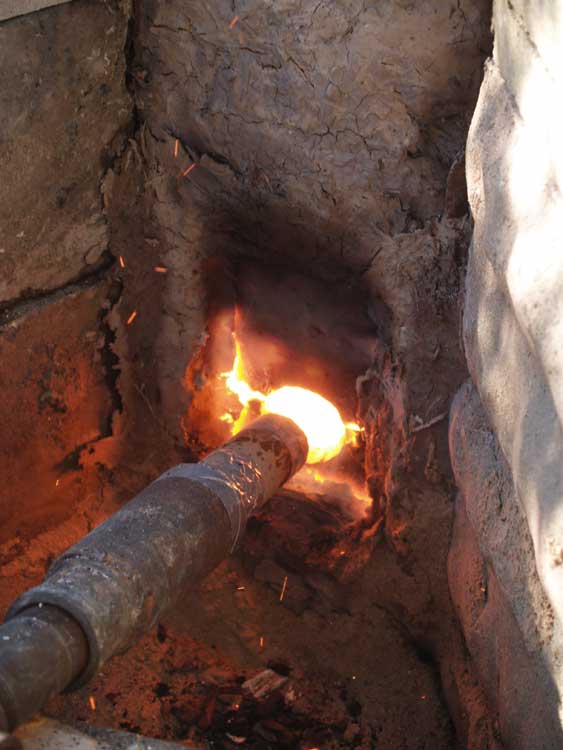
A bellows plate
and blow hole combination on a working furnace (October 2008)
The blow hole method employs a hole cut into the bellows plate. The usual practice
for current experimenters has been to size the hole to allow for about 1 cm
clearance around all sides of the air tube used. The air outlet pipe is actually
set back 6 - 10 cm from the hole. This distance, plus the cooling effect of
the air blast, means that even organic materials such as wood can be used without
danger of overheating. In effect, the air blast creates a venturi effect, which
actually draws significant amounts of the surrounding air into the furnace along
with that supplied by the blast itself. One draw back to this method is that
although air volumes are increased, the effective pressure of the blast is reduced.
This can mean that the air does not penetrate as far into the body of the furnace,
significantly changing the working dynamics inside the furnace. One clear advantage,
especially significant with human powered equipment, is reduced labour required
by the operators to generate the required air volumes.
One small fragment of clay wall material bearing the partial outline of a potential
blow hole has been uncovered at Hals. If this is what the fragment represents,
the indication is for a hole diameter roughly 4 - 5 cm. With the usual 1 cm
clearance, this would suggest an external diameter of 2 - 3 cm, certainly within
the range possible if a metal tube was employed. Michael Nissen has reported
on his use of a tapered iron (mild steel) tube. He has good results with a air
pipe outlet diameter in the range of 1.5 to 2 cm, working in concert with a
blow hole in the range of 2 to 4 cm. This hole diameter in the bellows plate
is based on a number of finds he has examined in Denmark.
(J) The report mentions "...a spray of charcoal in a wedge away from the
suspected tuyere / tap arch position.". This is perhaps indicative of bottom
extraction through a tap arch. This method would result in more damage to the
smelter, plus single firing smelts (rather than chain production as more possible
via top extraction). Balanced against this are the remains of the smelters themselves,
especially as seen on number VI. Here the tap arch diameter is indicated at 10
cm, and the bloom suggested at 15 cm wide (from depression in slag bowl). The
slag bowl is also relatively intact in a number of the furnaces excavated, more
damage to the bowls might be expected with side extractions. (A fuller discussion
of the two extraction methods create distinctive debris fields can be found in
'Adventures in Early Iron', Markewitz -2005)
(I) The experience of all those involved in experimental iron smelting has shown
the clear relationship between ore and smelter design and operation. Determining
the exact chemical composition of the ore used originally at Hals is thus extremely
important to a correct full reconstruction. The team is confident that the recent
work on the DARC Dirt 1 bog ore analog will prove of great value in matching
the chemistry once it is determined.
Experimental Variables:
Working measurements for testing a Hals
type furnace
Our experiments must test a number of individual elements that add up to the
full reconstruction (in no particular order) :
1) Working within a 2 m x 2m platform
2) Sod cone in a log frame construction
3) Hand powered bellows
4) Use of thin clay / marl liner on interior
5) Working down a narrow slot
6) Tuyere above tap arch set up
7) Stone slab front construction
8) Use of 'bellows plate' / blow hole arrangement
9) Use of primary bog ore material
1) The physical dynamic of working from up on top of a platform with the smelter
effectively at 'floor' level is not expected to present a major challenge. During
the building phase, the creation of the inner clay liner is expected to be more
difficult. The lower portions will have to be accomplished working laying down
and at full arms reach. (The smelter extends at least 60 cm, and normal arm
reach is only about that same amount.) During the main operation of the smelter,
adding charges of ore and charcoal are not expected to deviate too much from
established practice. At point of extraction, the operators will be standing
directly above the hot furnace, with their entire bodies exposed to the extreme
temperatures. Effective reach will again become a major factor in effective
removal of the hot bloom.
2) The sod construction represents a major logistics challenge at this point.
We will need a skid of grass sod (hopefully donated) plus a large number of
timbers (likely as fence post lengths) to construct the frame. For the initial
run of experiments, we can certainly use an earth banked design which will allow
us to test a number of the other elements. (Further discussion of this below)
3) The use of a hand powered bellows is not expected to be a major problem at
this point. A full test is more about labour organization than air delivery effect
on the smelt. A simple short duration test of the current bellows design with
a series of operators suggested that the average air delivery would be in the
range of 650 - 700 litres per minute. This compares with the expected
air requirements (Sauder & Williams plus past experience) between 580
to 880 litres per minute (for a 25 cm interior diameter).
4) Use of the thin liner should represent a major test on its own. We will have
to substitute a ball clay for marl (as we can't easily get any marl / 'glacial
blue' clay). The evidence from Hals does not appear to give us either the specific
thickness, or composition of the suspected clay liner. Kevin Smith has suggested
2 - 5 cm wall thickness. At this measurement, the horse manure mixture is likely
to perform better than our standard clay with straw cobb. We can expect increasing
fragility and reduced durability (erosion effects) as the clay layer is reduced
in thickness.
5) The overall work dynamic of the Icelandic smelter is the easiest thing to
test. Within the normal working area at Wareham, the overall layout can be simulated
out by digging a key hole into the side of the existing pond bank. This would
let us use the upper ground level as if it was the top of the sod construction,
blocking out the 2 metre square working platform. This would require us to undertake
all the physical adjustments to the smelt bowl working down a roughly 1 m long
slot. The position of a man powered bellows can be indicated by placing a plywood
cut out on to the existing heavy frame (from the failed 'Obberbellows'). With
a new construction, it will be simple to provide for a loose sand surface that
will provide a record of work and debris patterns.
6) One major shift from past experiments is the placement of the tuyere directly
above a small tap arch. (The normal layout has been with the tuyere set at right
angles to the tap arch, typically to the right hand side). This change in itself
is not expected to create any significant problems.
7) There have already been two experiments with stone slab construction (the Thanksgiving
and Fall smelts of 2007). For the first of these we did try to use the 'blow tube'
style tuyere (tuyere set back from blast hole), but with poor results. The use
of a stone front on the smelter (or entire stone construction) itself has been
tested to success.
8) The use of a separate clay bellows plate represents an archaeological question
at its core. Again, there appears to be no specific artifact evidence, but that
should balanced against the relatively fragile nature of these plates. A number
of smelts (mainly Nissen) have shown that a roughly 15 x 20 cm by 2 cm thick
plate of dry horse manure mixed 50 / 50 with clay works extremely well.
The second piece of this method is the set up with the tuyere actually sitting
proud of the smelter wall. I did use the combination of bellows plate (thin plate
around tuyere entry) with blow tube set up at Smeltfest
08 for two smelts with good results. Also watched Michael Nissen do this three
times in Denmark (2008). Overall, it should
be expected that learning to correctly operate a furnace using a blow tube will
present the most significant challenge in the experimental series.
9) Some continued refinement of the mix on the DARC Dirt 1 analog remains. Due
to bad communications (and poorer math!) the actual iron content of the first
round of test materials was really on the low end (at about 50 % Fe). It did
match the St Lunaire samples, but ideally the iron content should be increased
to something richer and more likely to give higher end yields. An effort should
be made to get samples tested from the ore found at Hals so we can try to match
the chemistry from Hals if at all possible.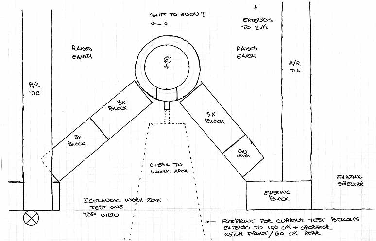
Plan view of the 'Work Dynamic Test'
layout (October 2008)
References:
Nissen, Michael. Jernmagerens Værksted. 2005 < http://www.jernmager.dk
>
Markewitz, Darrell. "Adventures in Early Iron" , 2006 . Experimental
Iron Smelting from the Viking Age, The Wareham Forge. CD-ROM, 2007
Markewitz, Darrell. Experimental Iron Smelting. 2001 - 2008 < http://www.warehamforge.ca/ironsmelting/index.html
>
Sauder, Lee & Williams, Skip. "A Practical Treatise on the Smelting
and Smithing of Bloomery Iron"
Historical Metallurgy, vol. 36 (2), 2002
Smith, Kevin P. "
Ore, fire, hammer, sickle: iron production in Viking Age
and Early Medieval Iceland.". De Re Metallica: Studies in Medieval Metals,
AVISTA Studies in the History of Medieval Technology, Science, and Art, Volume
4, edited by Robert Bork et al., pp. 183-206. Ashgate Press, Aldershot, UK.
2005
(Short Cut HERE back to the main
site index / map.)
Text and photography ©
1998 - 2008, Darrell Markewitz