Abstract
The creation of a forgeable iron bloom from raw ores is the result of a series of individual tasks, requiring many complex factors to be correctly integrated. An examination of the archaeological remains provides only a glimpse of the final stages of what is an ever changing process that unfolds over several hours. So just how was iron smelted during the Viking Age? Through a process of experimental archaeology, it may prove possible to work backwards from successful physical methods towards a process which employs only elements consistent with the technologies available historically. Working primarily with a team from Central Ontario, Canada, the author has to date undertaken 39 individual smelt sequences based on Viking Age prototypes. What has been learned from practical experience at the furnace may prove informative to researchers attempting to understand physical remains in the field.
Note: This paper has been revised from the original submitted in March of 2006, which only covered the first 13 experiments (to early 2006). What is seen here is the 'long version', before a further 2,000 words had been trimmed for submission for publication and with extra linked materials linked via the web. Those interested in seeing the original (2006) paper can find it as Adventures in Early Iron Production.
Introduction
In June of 2001, Parks Canada assembled a small team at L’Anse aux Meadows, National Historic Site of Canada, Newfoundland. The intent for the week long project was to develop the interpretive methods to be used in presenting a new reconstruction of House-site J, described as ‘the Smithy’ by A. Stine Ingstad / Eldjarn (1). The main feature of this structure was the fragmentary remains of what was interpreted as an iron smelting furnace. Part of the workshop was the construction and firing of a simple smelter, which served to initiate this experimental series.
From that date to the end of 2008, a total of 39 individual smelt experiments have been undertaken, with a similar number observed. The first objective has been to establish a consistent physical method that allows for predictable production of workable iron blooms. As the series progresses, modern elements are being replaced with more historically accurate ones, based on the archaeology of the Viking Age. The intent has been to gain practical experience in the overall process, leading eventually to a full reconstruction of a method that might have been used in Northern Europe during the Early Medieval period.
The Experiments
Please refer to Table 1 ‘Smelt Data’
Specifics of furnace construction, air systems and raw materials will be discussed below. The pioneering work of Lee Sauder & Skip Williams (2) has established many of the basic principles and working methods upon which the details under consideration here are based. There has been found to be a clear relationship between smelter size and layout, the ore type and particle size, and the charcoal particle size.
| Smelt 1 | Smelt 2 | Smelt 3 | Smelt 4 | Smelt 5 | Smelt 6 | Smelt 7 | Smelt 8 | Smelt 9 | Smelt 10 |
| Smelt 11 | Smelt 12 | Smelt 13 | Smelt 14 | Smelt 15 | Smelt 16 | Smelt 17 | Smelt 18 | Smelt 19 | Smelt 20 |
| Smelt 21 | Smelt 22 | Smelt 23 | Smelt 24 | Smelt 25 | Smelt 26 | Smelt 27 | Smelt 28 | Smelt 29 | Smelt 30 |
| Smelt 31 | Smelt 32 | Smelt 33 | Smelt 34 | Smelt 35 | Smelt 36 | Smelt 37 | Smelt 38 | Smelt 39 |
General Notes on Materials
Ores:
In almost all cases, the raw ores were roasted as the first step in their
preparation. This converts the various possible iron oxides into the magnetic
form Fe2O3 . A number of methods have been used to roast the various ores, primarily
based on ease of handling, and these are discussed with each ore type. It has
been found that the types of smelters and methods used in this series require
an ore with a minimum of roughly 60 % Fe2O3 / 40 % Fe content to yield effective
results. Regardless of the type of ore used, the ideal particle size for the
scale of smelters used in this series has been found to range from ‘pea
to rice’ size, retaining any dust produced in the crushing process. This
gives a size of 10 to 2 mm for the bulk of the ore added to the smelter, sorted
by eye.
Because of problems accessing a dependable source of suitable iron ore, a wide
range of types and qualities of ore have been used over the series. For that
reason, more experience has been gained with multiple ore types than is typical
for most experimenters.
Type |
Form |
Source |
Fe2O3 |
Fe |
SiO2 |
Al2O3 |
L’Anse aux Meadows |
bog |
L’Anse aux Meadows NF |
89 |
62 |
1.2 |
2.5 |
St Lunaire |
bog |
St Lunaire NF |
64 |
48* |
2.2 |
3.3 |
DARK Dirt One |
analog |
DARC ON |
65 |
45 |
15.5 |
2.3 |
Virginia |
rock |
Lexington VA |
(82) |
(58) |
? |
? |
Taconite |
pellets |
Stelco Canada |
92 |
65 |
4.9 |
2.2 |
Hematite |
grit |
Opta Minerals |
98 |
69 |
1.2 |
1 |
Table Two : Chemical contents (%) of various ores used
Fe2O3 and Fe values are calculated to allow comparison
* The St Lunaire material also included some Fe0 which is added to the total of Fe.
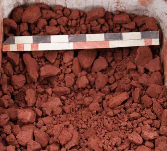
Primary Bog Ore
There is considerable confusion among the current generation of North American iron smelt enthusiasts about exactly which material the term ‘bog iron ore’ refers to. The term has come to describe materials with a wide range of physical and chemical properties, and seems to be applied regionally to describe any iron rich material, not obviously a rock ore, that is found in lumps near water. The term ‘primary bog ore’ is therefore proposed to describe an FeOOH material which:
- is newly formed
- is a product of the chain of iron rich bedrock, leached by tannic acid bog water then deposited via the action of bacteria along the margins of small streams immediately below the source bog.
For the initial test smelt at L’Anse aux Meadows in 2001, Dr. B. Wallace had provided a small amount of primary bog ore (about 2 kg) that had been gathered during her excavations of the site in 1974. Samples of this material were later analyzed (3) and found to be extremely high in iron oxide, with a Fe2O3 content of roughly 90%. (Smelt 1)
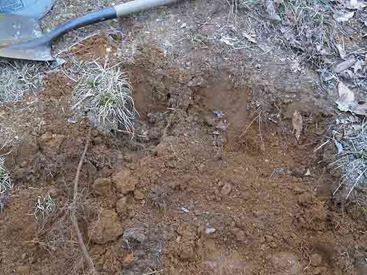
Armed with knowledge on how to spot likely primary bog ore deposits gained from
A. Espelund (4), a source was discovered close to St. Lunaire (about 15 km south
of L’Anse aux Meadows) . In about a hour roughly 22 litres of wet ore was
gathered. A sample of this
material was later analyzed (5) and found to average about 65% Fe2O3. (Smelt
2)
Because of their small particle size (roughly 5-10 mm), these bog ores were
heated to a dull orange (roughly 750 degrees C) on an open
pan inside a propane gas forge then air cooled.
Back in Central Ontario, deposits of primary bog ore have proved elusive. Totally by accident, a small deposit of a primary bog iron ore, in the form of a loose pudding like layer in standing water along a road side drainage ditch, was found near Minden. Only enough of this material was available for a small proof of concept test, and no analysis was possible. (Smelt 19)
During the 2008 ‘Iron Seminar in Thy’ symposium, there were three different primary bog iron ores available, from Guldager and Heltborg in Denmark, and Tranemo Sweden. No specific analysis of these ores was available, but the results suggest the Guldager and Heltborg ores had low iron contents. (Smelts 33 - 35)
DARC Dirt One
Because of the widespread use of primary bog Iron ores in the Viking Age, coupled
with the lack of this material in our region, some experimentation was undertaken
to create an effective bog iron analog. Initial research was by team member
Robert Gissing, followed by development of useful scale production methods and
smelter testing. The main element of ‘DARC Dirt One’ is commercially
available ‘Spanish Red’ iron oxide used by potters. This material
is mixed with about 10 % silica sand and 10% of an organic binder to result
in an ore material
with Fe2O3 content about 65%. This analog thus approximates the primary bog
iron ore gathered from St Lunarie. This material was not roasted before use,
and the particle size was larger, typically 10 mm thick and ranging between
25 x 25 mm to 5 x 5 mm. Work continues on this analog, with a paper detailing
the research planned. (Smelts 30, 32, 36)
Virginia Rock Ore
Sauder and Williams have long used a locally available geothite rock ore, which
they gather from abandoned Colonial era mine works near Lexington Virginia.
They have assessed this material as containing an average of 60% iron content
(6), so Fe2O3 at about 85 %. When gathering the Virginia rock ore, an attempt
is made to select pieces that experience indicates (by their colour and texture)
would have higher iron content. For ease of handling, pieces roughly fist sized
or slightly larger have been chosen. All the rock ores were roasted by baking
in an open wood fire, then raking out from the ashes. As suggested by Sauder,
hot pieces are quenched in water to shatter the stone and make them easier to
break to size with hand hammers. Smelts 3 - 8, 12, 13, 17, 18, 20 -22, 29, 30
On a second visit to the mine source, the author’s less experienced eye
resulted in a poorer grade of ore to be gathered. There is no specific iron
content analysis available for this material, which is referred to in the table
as ‘Virginia (poor)’ It has most frequently blended with the high
iron / low silica hematite grit. (Smelts 24, 25,27, 38, 39 )
Williamsburg Rock Ore
In 2008 it was possible to gather a quantity of alluvial deposit geothite from
a location just outside of Williamsburg VA. This
material is actually from the eastern edge of the same seam running under
the Blue Ridge as the Lexington material. In ancient times it had been eroded,
then washed down to be deposited in sand banks along what then was the ocean
shore. Although this material has not been tested for iron content, its performance
in the smelter is so similar to the Lexington material that it is likely quite
similar. (Smelt 37 )
Taconite
Through the assistance of the Ontario Artist Blacksmith Association, roughly
100 kg of processed taconite pellets were acquired. This is the same raw material
used for industrial steel smelting in Hamilton Ontario. It was also possible
to get a copy of the chemical analysis for the material, which indicates an
Fe2O3 over 90% . (7) This material was typically roasted by heating on a shallow
pan inside a propane gas forge then quenching in water to assist the manual
breaking step. Smelts 9-11, 14, 26, 28
Hematite
In an effort to find a dependable industrial source for iron oxides, a quantity
of hematite blasting grit, mined in Quebec, was purchased from Opta Minerals.
This material is extremely rich, at 98% Fe2O3 (8). Its main draw back is an
extremely fine particle size, screened to .5 mm. This most often results in
a much higher carbon absorption rate than the other ores used, at least inside
the standard furnace dimensions. For this reason it is often used blended with
poorer quality ores. This material is not roasted before use. (Smelts 15, 16,
23, 25, 27, 38, 39)
Clays:
A number of different clay bodies have been used for smelter construction
. Starting with Smelt 12, it was realized that the low cost of powdered potter’s
clays more than offset the huge labour required in preparing ‘free’
natural clays. For that reason commercial ball clays have been used to construct
the clay cobb smelters used for the bulk of the series.
Early smelters constructed of solid clay generally proved less durable and more
susceptible to wall erosion, the melting temperatures of the individual clays
always being well below the internal working temperature of the smelter. There
were so many advantages to clay cobb construction, use of straight clay walls
was abandoned.
Clay Cobb
In most cases, the Short Shaft furnaces have been constructed of the selected
clay mixed with chopped straw to produce ‘cobb’. Local straw from
cereal grains (baled for animal bedding) was chopped with a hand axe to a rough
length of 7.5 cm. There was a certain randomness to this process, resulting
in individual shaft lengths ranging generally from 5 to 10 cm long. Because
the source material had been gathered from the field as an agricultural process,
the individual pieces varied considerably in diameter, and included both plant
stocks and leaves. The normal mix was about equal volumes of wet clay and chopped
straw. Additional water was added as required to permit mixing by hand. A small
amount of course beach sand (dug locally) was added as required to stiffen the
mix.
For the furnace used for both experiments 10 & 13, sphagnum moss was used
as the binder. This was done primarily to test another possible material that
would have been available throughout Northern Europe. Generally the moss proved
not as effective as the straw. It absorbed a considerable amount of water during
the mixing, increasing the drying time required at the preheat phase. It also
did not give as great a structural strength to the finished smelter. The loose
sphagnum proved much more difficult to acquire and was quite expensive.
The cylindrical bodies of the furnaces have been built both ‘free form’
and also by packing the prepared clay mixture between sheet metal forms. This
second method greatly speeds construction, and also allows for creation of a
very standard size and shape of test smelter. An internal bundle of wood slats
(Smelts 15, 16) or sticks and straw (Smelt 18) has also been used to replicate
a more historically based method of framing.
Charcoal:
Each individual smelt consumes anything from 50 to 100 kg of prepared charcoal. Most of these experiments have used various commercially produced charcoals, primarily oak or hickory. Generally it has been seen that the most significant factor between different sources has been how dry the charcoal is, the drier the fuel, the more efficient the burning.
For experiments 1 & 2, charcoal was used ‘straight from the bag’ with no attempt to grade for size. Starting with experiment 3 to 6, charcoal was sized into roughly 2.5 cm pieces by use of a combination of cutting with a hand axe and smashing with wooden mallets. Dust and fines were screened out by straining through a roughly 1.2 cm grid. These fines are set aside for use as base packing and a surface for trapping any tap slag.
Because of the time involved in preparing the volume of charcoal required for an individual smelt, a heavy metal frame was created and used starting with experiment 7 . The charcoal is broken and sized by pounding through a 2.5 cm grid with wooden mallets. Fines are sorted out by a lower diagonal grid with about 1 cm spacing, and retained for packing furnace bases, etc.
Smelter Equipment
Primary Smelter Types:
Although there have been a number of smelter classifications suggested (Cleere
- 1972, Tylecote - 1987, Pleiner - 2000) , archaeology rarely preserves the
upper portions of ancient smelters. An alternate set of terminology is used
here, referring to size , construction details, and air supply system used.
‘Boxed Bowl’
For the first two smelts, the overall form
of the smelter was based on what was understood to have been used at L’Anse
aux Meadows circa 1000 AD. The details were supplied by Dr Birgitta Wallace
(9), in turn based on her understanding of the archaeological remains at that
site. What was suggested was a square box composed of local stone slabs, roughly
40 x 30 cm at the base, and about 40 cm tall, with the corners sealed with clay.
The experimental furnaces of this type have used randomly selected gneiss slabs,
chosen primarily for the shape of the individual pieces and ease of collection.
As the first two experiments, these smelts should be really considered tests
of establishing an experimental technique and possible equipment types. Latter
experience would show that almost every mistake in furnace layout and smelting
process possible had been made! Much later (Smelt 27) a modified version utilizing
higher shaft walls (to + 60 cm) would prove effective. Future experiments are
planned working towards a possible L’Anse aux Meadows model.
‘Short Shaft’
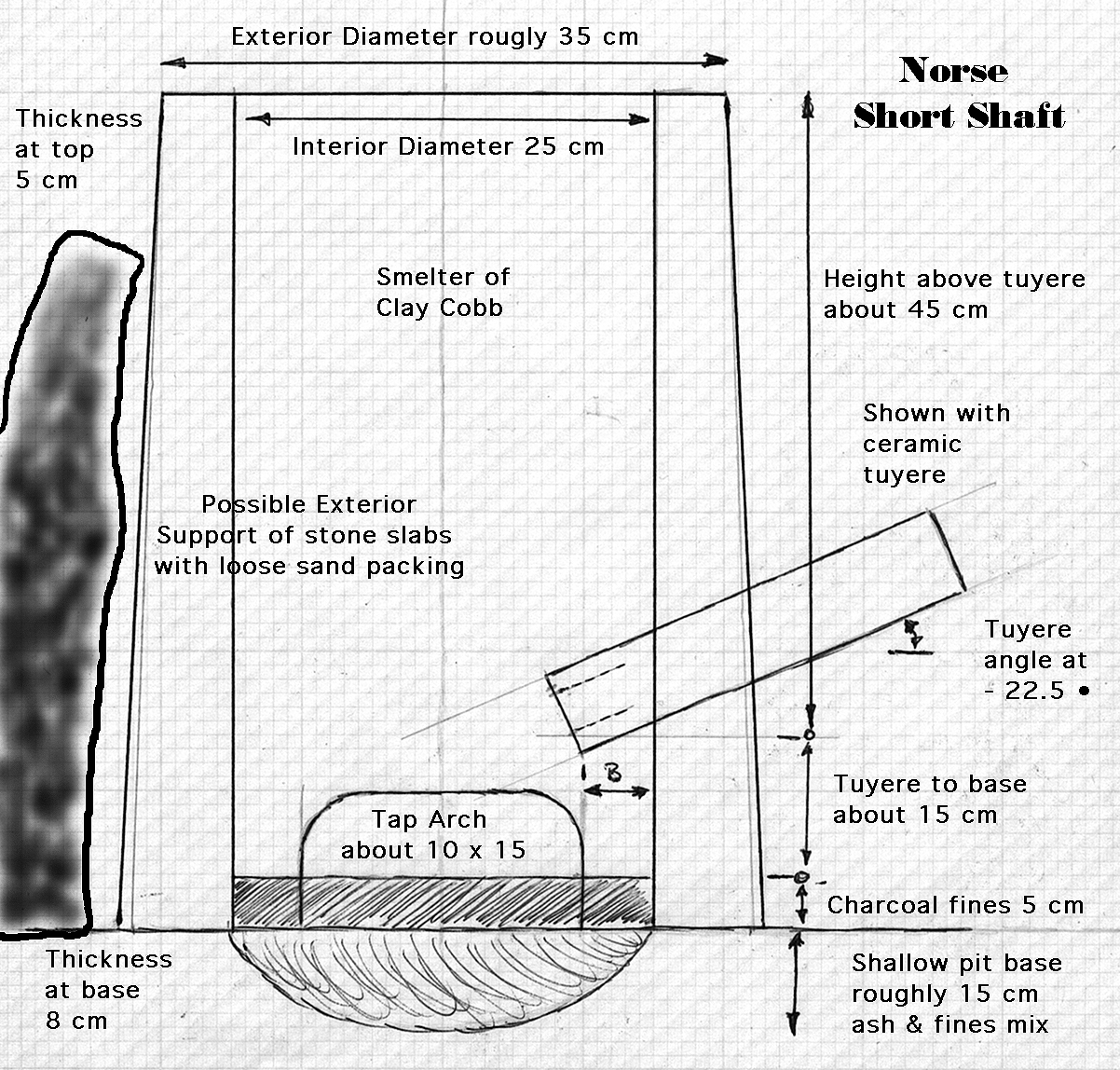
Figure 1 - Standard ‘Short Shaft’ Smelter
After a number of initial failures, it was decided to confine furnace construction
to a relatively standard
form, loosely based on Viking Age prototypes. This standard smelter has
an interior diameter of between 25 - 30 cm, with a total wall height of roughly
60 cm. Walls are built of clay cobb, with a typical thickness of 7.5 cm. There
is normally a tap arch, typically about 10 cm tall and 20 cm wide at the base.
Normal practice has been to offset the position of the tuyere by 90 degrees
to the tap arch. There will normally be at least 40 cm of stack height above
the tuyere. (Smelts 4, 5, 10, 11, 15 -19, 21, 22, 24 - 28, 36 - 39)
‘Boxed’ / ‘Banked’
To date, these extra descriptive terms have been applied to the Short Shaft type, indicating extra features of construction.
A ‘Boxed’
furnace will consist of a standard Short Shaft, which has then been surrounded
by a number of large stone slabs. The gap between the furnace body and the slabs
is then filled with loose sand. This was a method mainly used for early smelters,
when it was not known if the clay cylinders would survive the smelting process.
It was soon found that a properly constructed free standing furnace would in
fact survive multiple uses, and the method was abandoned. (Smelts 4,13,18 )
A ‘Banked’
furnace is set between half to three quarters into a n earthen bank, covering
the furnace to its top edge. Construction of this type started with the building
of a dedicated smelting work area in summer of 2006. Although not required for
support of the furnace itself, use of this method has two advantages for the
smelting process. Work both the rear (top extraction) and front (tuyere clearing
and front extraction) can take place at what is effectively ‘ground level’.
As the current work towards recreation of the furnaces excavated at Halls Iceland
by Kevin Smith goes forward, experience gained with the Banked construction
is proving most valuable. (Smelts 21, 22, 24 - 27, 36, 38, 39)
‘Medium Shaft’
A smaller number of taller furnaces have been built and used. For classification,
any furnace with a total wall height over 80 cm has been grouped here. (Smelts
3, 15, 29-31, 33-35)
‘Econo Norse’
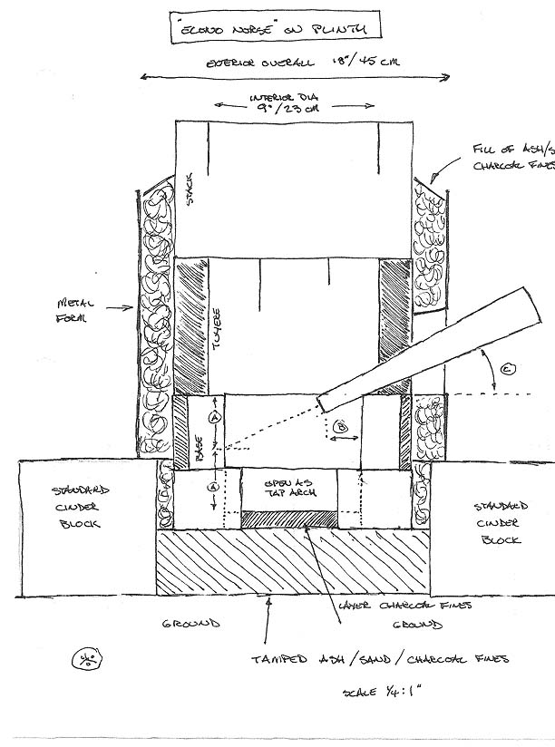
Figure 2 - Econo Norse Smelter
With involvement in the Early Iron series of symposiums, a simple to build
teaching and demonstration platform was designed. The ‘Econo
Norse’ has roughly the same functional measurements as the Short Shaft
type (roughly 25 cm interior diameter by about 60 cm high). It is constructed
of a ring of standard fire place bricks stood on end on top of an ash or charcoal
fines packed plinth formed from four concrete blocks. Three such rings are placed
one atop each other to form the body of the smelter. The bottom ring has one
full brick placed over two half bricks to form a tap arch. Either a gap in row
two or a specially drilled brick serves to mount the tuyere. The whole is encircled
by a sheet of sheet metal, held loosely in place with fencing wire. The space
between the exterior shell and the bricks is filled to both stabilize the construction,
but also to seal any small gaps between the bricks. Several different mixtures
have been tested, with the most effective being found to be a blend of half
wood ash and half course sand. One of the advantages of this design is its ability
to be disassembled ‘layer by layer’. This makes for easy top extraction,
but also allows for continuing to fire the furnace as a giant forge to assist
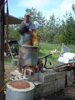
in compacting the bloom. (Smelts 6-9, 14, 23) Details of the construction
can be found : Econo Norse
‘Flue Tyle’
This is another teaching
and testing furnace, developed by Sauder, Williams & McCarthy (10) and
used to great effect at the Early Iron symposiums. At its core is a standard
red ceramic flue lining tile, roughly 28 cm square by 60 cm tall. The ceramic
is reinforced by covering it in a layer about 2 cm thick of a mixture of half
and half by volume of dry potters clay and shredded cellulose insulation mixed
with water. This layer is secured by tightly wrapping the exterior with chicken
wire. Once again the furnace is mounted on a base plinth of concrete blocks.
The Flue Tyle operates differently than the other furnaces described here in
that it relies on the thinness of the walls to radiate off excess heat to prevent
then from simply melting at smelting temperatures. (Smelts 12, 20) Details
of the construction can be found : Flue
Tyle
Air Supply
The initial experiments in this series started with the use of hand powered
re-creations of Viking Age type bellows. After repeated failures, It was decided
to utilize more dependable (and less labour intensive!) electrically powered
blowers. Generally there has been an attempt made to stick to standard pieces
of equipment.
A number of mechanical air delivery systems have been utilized for portions of individual smelts (often for the simple reason of equipment failure while a smelt was underway!). Experience has shown that centrifical blowers intended as blacksmith’s forge blowers (either hand or electrically driven) do not function effectively as smelter air supply. Such units may produce large volumes of air, but there is so little pressure produced that the air simply does not enter the furnace against the construction of the tuyere and the charcoal filled shaft.
Air volumes reported here have been calculated from flow speeds recorded by a vane type anemometer. After Smelt 29, these measurements were made ‘in line’ and so represent the actual air flow into the smelter body.
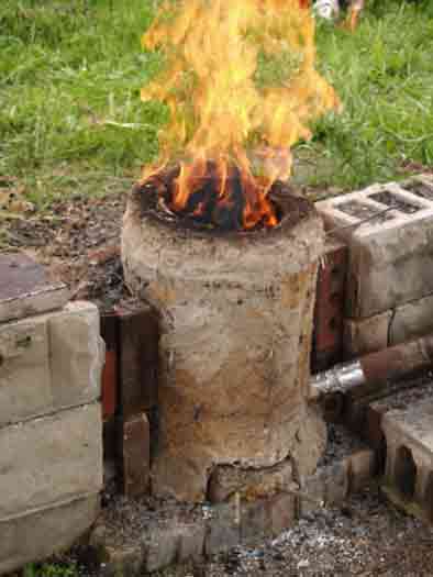
For the bulk of this series, the air supply has been attached
to the tuyere via a length of flexible hose, attached to a T shaped fitting
(seen in foreground - Figure 3 ) . This assembly is constructed from
standard 1 1/4 inch OD galvanized pipe fittings, allowing for ease of modification
as required. A ‘T’ connector is set so the inlet air is supplied at
90 degrees to the tuyere. An end cap with a clear viewing plate is fitted opposite
the tuyere allowing for direct viewing of the smelter interior down the tuyere.
The viewing port can be unscrewed, allowing for any blockages to the tuyere
to be cleared with a long steel rod (a process that has come to be known
as ‘rodgering’). The exact amount of air supplied to the tuyere is
controlled by a sliding blast gate set just downstream of the blower. This connection
system was adapted from that used by Sauder and Williams.
The two earliest smelts, and the three Viking Age presentation smelts (10,11,13
) did not use this system. In these cases, the outlet of the bellows used was
attached directly to the tuyere via a cylinder of leather. This creates a flexible
coupling, preventing any motion from working the bellows from affecting the
tuyere itself.
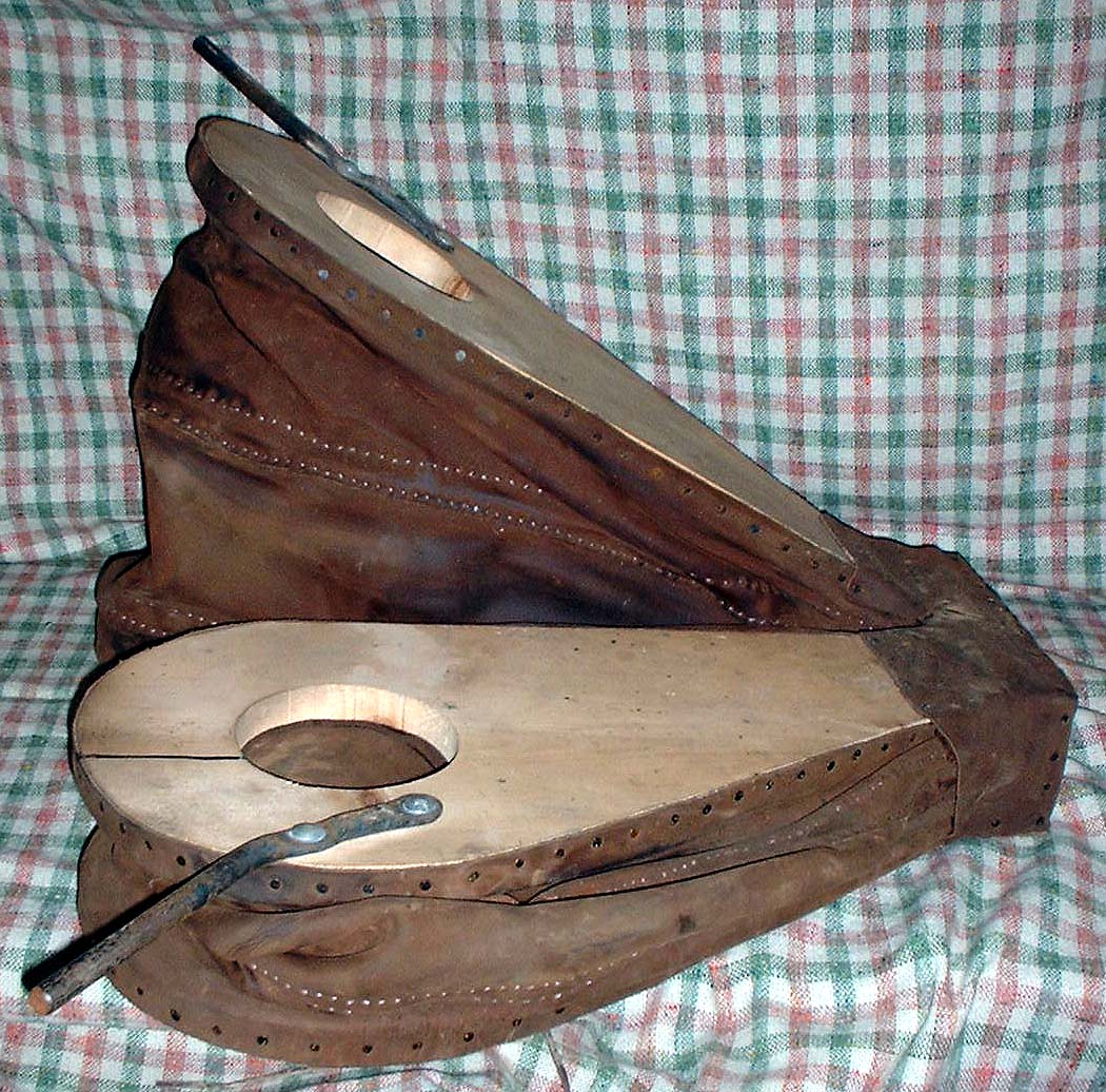
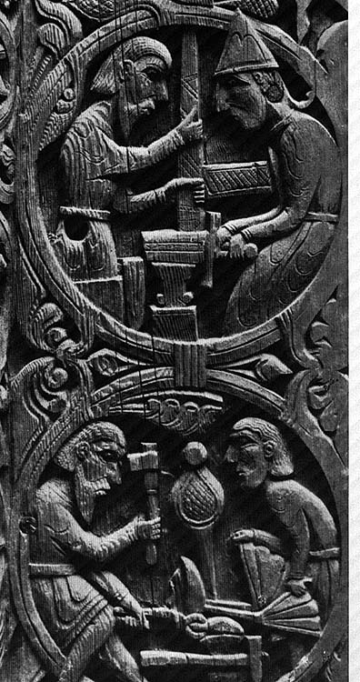
‘Norse Double Bag’ (NDB)
The shape of the very earliest experiments was guided by a desire to emulate
historic Norse forms. One of the primary features was thus the use of a reconstructed
Norse Double Bag bellows
system, a piece of blacksmith’s equipment. Unfortunately the artifact evidence
for these bellows is almost nonexistent; there are no surviving physical remains
and there are only two known period illustrations. One from the Urnes Stave
Church at Hylestad Norway, (late 1100’s) is a side
view, shown in relation to a human operator. The second is top view, from
a rune stone carving at Ramsund, Sweden.
From 1998 through 2008, a number of trial version bellows were constructed based on measurements estimated from these illustrations. The rough size of the reconstruction is 70 cm long by 50 cm wide overall. Each of the main chambers is about 50 cm long by 25 cm wide, in comfortable use providing a loft of about 30 cm. Each air inlet is 10 cm in diameter,with the outlet being a simple Y tube with roughly 2 cm interior diameter. Average air delivery is about 2.2 litres per stroke. In use, it was found that the average operator can maintain an effective pump rate of roughly one stroke per second, creating an air volume to the smelter of approximately 130 litres per minute.
Since this rate is only 25% of the ‘ideal volume’, the early experiments
using this air system were seen in retrospect to show all the classic signs
of an ‘under blown bloomery’. After Smelt 5, use of the Norse Double
Bag system has been suspended pending further testing and development. (Smelts
1, 2, 4, 5 )
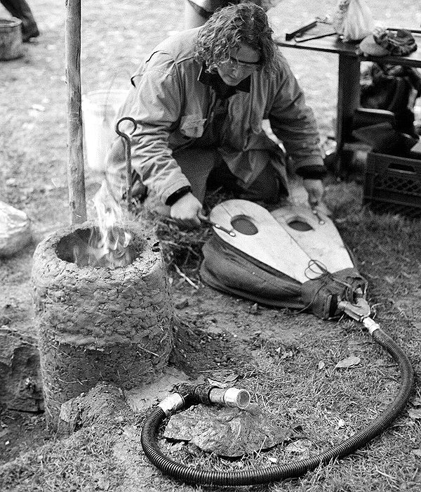
Figure 3 - The Norse Double Bag Bellows in action (Smelt 5).
‘ Über Bellows’ (UB)
A super sized version of the double bag bellows was created for public demonstrations
undertaken in 2005 & 2006. This unit, christened ‘the
Uber Bellows’ had individual bags with a length of 100 cm, and a width
of 20 cm, with a typical loft of about 50 cm for each stroke. A rate of roughly
8 to 10 strokes per minute could be maintained, but with considerable operator
fatigue. The delivery volume was estimated at an effective maximum of 90 litres
per stroke, thus potentially 900 litres per minute.
In practice, it was found that this system was less than ideal for a number
of reasons. Its use was abandoned after only three attempts. (Smelts 10, 11,
18)
Vacuum Blower (VAC)
Despite disparaging comments made by some researchers, vacuum cleaner blowers
have been proven to be both dependable, easy to acquire, and simple to adapt
as air supplies . Starting with experiment number 6, a single dedicated electric
blower of this type was used. The motor was matched to an electric supply that
could be modified via a calibrated light dimmer switch, thus creating a simple
speed and volume control. Later anemometer measurements indicated air volumes
ranging from about 170 litres up to 850 litres per minute. This brackets the
volumes available through use of either the Norse Double Bag or the Über
Bellows. This system has been used for the bulk of the experiments up to March
of 2008. (Smelts 3, 6-8, 12-17, 19, 21-28, plus portions of 9, 10)
A special case are the three smelts carried out at the Iron Seminar at Thy,
Heltborg Denmark in Spring 2008. Almost all smelt researchers in Denmark appear
to use the identical vacuum blower, a type not available in North America. These
are listed as ‘Denmark VAC’. (Smelts 33-35)
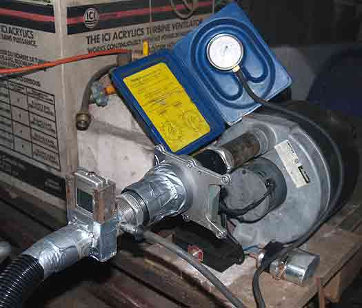
Electric Blower (blower)
In winter of 2008, an industrial
multi-stage centrifical blower was purchased. This unit, rated at 50 CFM
(1400 L/M) is identical to those used by Sauder & Williams (and thus also
used for some earlier experiments). (Smelts 12, 20, 29-32, 36-39)
Tuyeres
A general survey of Northern European archaeological finds related to smelting
and casting suggested that the most common interior diameter for tuyere tubes
of all types was about 2.5 cm. For this reason, all the tuyeres used have been
selected for this size, regardless of the material from which they are constructed.
The standard arrangement has been to use an insert style tuyere, typically standing
5 cm proud of the interior furnace wall.
Steel Pipe
The earliest experiments used standard Schedule 40 mild steel pipe, cut to 30
cm lengths. This material sometimes experienced significant erosion in the high
temperatures inside the furnace. This effect can be minimized by the correct
tuyere placement (discussed below), and is balanced by the fact the pipe is
cheap and easy to replace even in mid smelt. (Smelts 1-6, 9-11, 33-35)
Forged Copper
A suggestion by Kevin Smith (11) on the possible use of copper tuyeres historically
led to some experimentation with this material. Several tuyeres were forged
from pieces of scrap copper plate and tested at a workshop by Sauder, Williams
and McCarthy in February 2005. The resulting conical shape that varied in thickness
from roughly 3 mm at the air supply end to about 7 mm thick at the smelter end.
The interior diameter at the insert end was 2 cm. These copper tuyeres proved
extremely durable when used in conjunction with the thin walled ‘Flue Tyle’
test furnace. Smelt 12
Two tuyeres were also formed from 1/8 inch thick (about 3 mm) copper sheet.
The interior diameter at the smelter end was roughly 2.5 cm. It has been found
that the key to successful use of any copper tuyere is to ensure that as little
as possible of the material is in contact with the furnace walls. Outside of
the smelter, the high conductivity of the copper allows it to radiate away the
heat to which its working tip is exposed. (Smelts 7, 8, part of 9)
Ceramic Tube
An ideal ceramic tuyere was found to be commercially available, designed as
supports for pottery kilns firing porcelain clays. These are a straight cylinder
30 cm long, with an interior diameter of 2.5 cm with a wall thickness of roughly
1.2 cm (1/2 inch). Each is rated to withstand temperatures in excess of 1200
C - close to the operating temperatures inside an iron smelter. As these tubes
are inexpensive and have proved quite durable, they have become the standard
tuyere for continued experiments. (Smelts 13-28, 32, 36, 37, part of 38)
Blow Hole
In the latest experiments covered by this report, work has begun to accumulate
practical experience with the combination of bellows plate and blow hole. This
method was introduced via Skip Williams (12) based on his experiences at ‘The
3rd International Symposium on Early Iron’, Eindhoven, Holland, 2007. Further
observations of Michael Nissen’s use of the technique were made at ‘The
Iron Seminar at Thy’, Heltborg, Denmark, 2008.
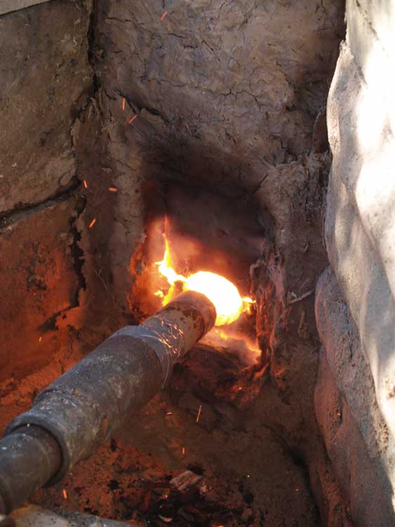
Figure 4 - Bellows Plate and Blow Hole (Smelt 38)
This system uses a thin clay cobb plate, typically 1.5 to 2 cm thick by roughly 15 cm wide and 20 cm tall, inset to sit flush with the inside of the smelter wall at normal tuyere level. The cobb is composed of a mixture of half clay and half dry shredded horse manure. The plate has a hole cut into it along the mid line and roughly 1/3 up from the bottom edge. The size of this hole is dependent on the size of the air tube / tuyere, ideal appears to be an additional 1 cm gap around the tuyere circumference. There will be a gap between the tip of the tuyere and the surface of the plate. The exact position of the tuyere varies, and is adjusted by sound (and experience!). As the air delivery tube is not in physical contact with the smelter itself, the heat effect on the tube is minimal. (Smelts 29-31, 38, 3)
Towards an Effective Smelt
Reduced to its simplest terms, hot C0 gas moves upward from the area of the tuyere inside the furnace. Ore particles are reduced as they fall down reducing to metallic iron and leaving CO2 to be expelled. The hot iron particles sinter, falling to rest just below the tuyere on top of the semi congealed slag bowl, and protected from the oxygen of the air blast by a pool of liquid slag.
The first goal of this series has been to establish an smelter design and working
sequence that consistently will efficiently produce good working quality iron
blooms. Ore type and iron content then remain the single largest variables.
The ideal is a dense, plano-convex, roughly oval mass of low carbon iron. Using
a 60 % Fe / 85 % Fe2O3 ore, the expected yields have been in the range of 25
- 30 %.
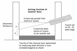
Smelter Layout: (please refer to Figure 1)
Without enough stack height above the tuyere, there is not enough of a reaction column to allow for the required chemistry to take place. For the standard sizes and volumes described, it has been found that the minimum effective furnace height above the tuyere is 40 cm.
After the first initial failures, and for most of the experiments, setting
an ideal base inside the smelter was considered of great importance. This
was done by placing a layer of charcoal fines in the bottom of the furnace,
of a depth so to leave approximately 15 cm clear below the tuyere. Although
proven to be effective in establishing the location of the slag bowl, and making
bottom extraction of the bloom much easier, this method is certainly not indicated
by archaeological remains. Starting with Smelt 22, most of the furnaces have
a natural base composed of wood ash and partially burned charcoal from the preheat
step. Despite earlier concerns, it has been seen that creating a specific base
level is not necessary to an effective smelt. It has also been found that there
is virtually no heat penetration below this ash layer to the soil underneath.
Air:
It has been demonstrated by Sauder and Williams (13) that in fact a successful
smelt is most likely when high volumes of air are supplied. They have suggested
that an ideal rate of 1.2 to 1.5 litres per minute for each cubic centimeter
of the smelter base cross section. The experiments described here also support
this conclusion. For the smelter size that has come to be standard for this
experiment series (average between 25 to 30 cm diameter) this translates to
effective air rates in a range between 560 to 1060 litres per minute.
Of course any reaction is also dependent on time. For these furnaces, burn rate is always closely monitored, being the time to consume a standard charcoal measure. Typically this is about 2 kg (or about 10 litres), the ideal consumption rate found to be one such measure every 8-10 minutes. For most smelts a working range of between 6 - 12 minutes is allowed before any modifications need to be considered.
Tuyere:
During the workshop session with Sauder, Williams and McCarthy in February of 2005, a set of test smelts determined that the angle of the tuyere has a pronounced effect on the formation of the bloom. At least for smelters in the size range under discussion here, it has been found that the most effective tuyere angle was from 20 to 23 degrees down from horizontal. At angles below -15 degrees, typically the slag bowl forms too high, not leaving much room for the developing bloom and the shallow slag bath drowns the tuyere. At angles much higher than -25 degrees, the blast from the tuyere effectively cuts away into the bloom.
Position of the tuyere tip related to the smelter wall, and the durability of the tuyere allowing it to maintain that position, has also been discovered to be of importance. Again for smelters of this size range, inserting the tuyere so it extends 5 cm beyond the inner wall has been found to be ideal. As the tuyere tip approaches the inner wall, excessive erosion of the smelter containment, especially just above the tuyere, is most likely to occur.
Although direct experience with the bellows plate and blow hole combination is limited at time of writing (only five smelts) the results have consistently been smaller, crescent shaped and more sponge like blooms - rather than the dense ‘pucks’ created with using insert tuyeres. This is attributed primarily less penetration of the air blast into the furnace body, changing the dynamics of the effective heat zone.
Ore Addition:
Consumption rate can also be controlled by varying the amount of ore added. The ore charge is distributed evenly through the addition each charcoal bucket, not applied as a thick layer as is often illustrated. The charge is sprinkled over the smelter mouth, exact location varies with the burn pattern visible in the charcoal. With charcoal being consumed at the desired rate, any given particle of ore is inside the reactive gas column for about 30 - 40 minutes. The size of peak ore charges have varied between individual smelts, but commonly reach 2 kg ore to each 2 kg of charcoal, added every 8 minutes.
Across this series, it has been found that there is a bottom threshold on the
amount of ore required to create the interior environment that leads to bloom
formation. Although the silica content of the ore is certainly a factor, about
8 kg of ore has been required for smelters of this type to form the slag bowl
and start the growth of a solid bloom.
Some Possible Ramifications with Regard to the Viking Age
Air Supplies:
The various reconstructions of a Viking Age double bag bellows produced simply do not produce air volumes large enough to successfully produce a large and dense iron bloom. The experience of many experimenters is that a low air volume smelt will result in small sized and lacy or bubbly blooms, which in turn are extremely difficult to consolidate into useful iron bars. This contrasts quite sharply with the quality of known artifact blooms. Overall this suggests that the single Norse Double Bag bellows, as directly based on the historical evidence, was a tool primarily intended for the blacksmiths forge - not the iron smelter.
Now, a number of the smaller ‘blacksmith’ units, linked via an animal skin bladder, could certainly provide the air volumes required. With the addition of a simple inlet-only valve at each attachment point, plus the use of a plank with a stone weight, a constant air flow to the tuyere would be created. This system will average out variations from individual operators, plus gives a constant flow, rather than the pulsing air delivery created from the action of a single unit. Modifying delivery pressure could be accomplished by changing the stone weight. This will shift the location of the ‘hot spot’ inside the smelter which, in turn, could affect the size and shape of the developing bloom in a positive manner.
By extension, this system suggests a different social organization surrounding certain types of smelting operations. Like house raising, ship building and other high labour projects, these smelts might have gathered together a number of local households, perhaps then moving in rotation among them. Those researchers knowledgeable in social structure or rural lifestyles are certainly encouraged to examine this possibility.
Perhaps the simplest conclusion is that a bellows intended for iron smelting
use was simply larger, and that samples of this type have yet to be uncovered.
Ongoing tests in this area have suggested that increasing the single bag measurements
to 30 cm wide and 65 cm long will provide dependable air volumes in the range
of 750 litres per minute. Careful examination of known smelting sites for the
void patterns in debris that would be caused underneath working bellows may
provide valuable insights.
Working Patterns:
There are two ways normally used to extract a final bloom from the smelter. Each presents different advantages and problems for the iron master. The two methods also present different physical remains which may prove indicators to archaeologists. Observations of debris from single event smelts have even shown clear voids indicating location of the workers.
Front extraction is best suited to large sized blooms, and requires smelters either set totally above ground level or having quite large pits in front of the structure. One other advantage to this method is that the workers are able to shield themselves from much of the intense heat of the smelter interior by keeping their bodies to either side of the smelter as its base is opened, working with long handled tools at full arms reach as much as possible. This method requires either greatly enlarging the size of the tap arch, or digging away underneath the base of the smelter - often both. Typically there is considerable damage to the lower front of the smelter, especially when removing a large bloom.
When the furnace is opened at the bottom front, any burning charcoal and loose slag fragments are raked away from the inside of the smelter below the slag mass. When the smelter is set above ground, this hot debris is raked forward of the smelter, and then shoved off to either side out of way of the workers. Next, the front portion of the slag bowl is chiseled off to expose the bloom, which also will drain any remaining liquid slag (forming sheets). This action tends to break much of the slag bowl, still yellow hot, into large lumps. These are in turn pulled out and tossed to the sides, or away from the working area entirely. Next the hot bloom itself is pulled out of the smelter, using a hooked iron bar or special large bloom tongs. As this is done, the burning charcoal remaining above the bloom is pulled free, and tends to fall down to the bottom of the smelter and spray outward from the opening.
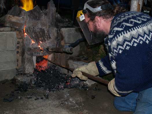
Figure 5 - Starting front extraction by clearing charcoal below the slag
bowl. (Smelt 27)
After extraction, much of the slag bowl is likely to remain in place inside the furnace, leaving a distinctive, roughly C shaped mass. If the furnace is to be reused, it has certainly proven easier to break up and pull away this mass while it still is hot.
The other possible method is withdrawing the mass out of the top of the smelter. This method is ideal for smaller sized blooms, which has been the objective of most of these experiments. Its main disadvantage is in the extreme heat faced by the individual who physically uncovers and pulls out the bloom from the incandescent interior of the smelter! The entire process must be undertaken with a reduced air blast through the tuyere which keeps the liquid slag pool from freezing and locking the bloom solidly in place.
A smelter intended for the top extraction method needs only a small tap arch, used for decanting liquid slag as required during the firing. A small tap arch adds to the stability of the structure, and requires less patching if reusing the smelter.In this method, a long handled metal scoop is used to scoop out all the remaining burning charcoal from inside the smelter, until the top of the molten slag pool covering the bloom is exposed. Assuming a right hand operator, this charcoal is typically dumped in a distinctive pattern the rear of the smelter (away from the tuyere and the bellows operator). This material may also contain lumps of partially reduced and loosely sintered ore which had not incorporated into the bloom (from the last ore charge added.). In many of the experiments, some liquid slag itself was scooped out at the end of this sequence, resulting in a spray of molten iron rich slag droplets deposited on top of this charcoal.
![]()
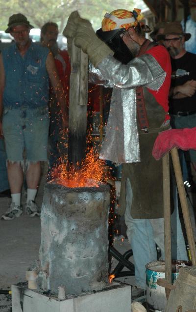
Figure 6 - Scooping burning charcoal before extracting the bloom from the top.
Note burning charcoal deposited to the right. Tap arch towards camera. (Smelt 10)
Photograph by Neil Peterson
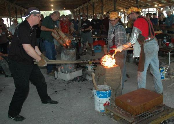
The next part of the process is to use
a log ‘thumper’ to strike the top of the bloom in place, a method
adapted from that used by Boonstra, van de Manakker & van Dijk (14). As
the bloom forms just below the tuyere, special care must be taken not to strike
the tuyere itself. This process has several effects on the bloom. First, as
the bloom is just at welding heat, striking it serves to compress much of the
lacy ‘mother’ material into the mass - with less loss than when the
bloom is extracted before any hammering. Hammering in place also serves to loosen
the metallic bloom from the semi-congealed slag bowl underneath it. Next a bloom
hook is forced down and underneath the edges of the bloom to pry the mass up
and free from the slag bowl. Once loose, large bloom tongs can be used to grab
the metal mass and pull it up out of its position in the slag bowl - and free
of the smelter.
If the air flow was cut at this point, the slag bowl, virtually intact, would
freeze in place inside the smelter as one piece. It would display the well known
clyndrical shape with concave upper surface. The top surface would have some
charcoal deeply embedded around the edges as a result of the pounding from above.
The lower surface would have more the appearance of tendrils running down and
around charcoal lumps. One other huge advantage of extraction from the top is
that there is very little damage , if any, to the structure of the smelter.
If the process of extraction is preformed quickly enough, it is quite possible
to fill the smelter with fresh charcoal, and with increased air blast quickly
restart the fire. This allows for use of the smelter as a giant forge for further
work on the bloom. More importantly, as the smelter is not significantly damaged
by this method, and retains the bulk of its internal temperature, it should
be posible to immediately restart a second smelt, the main limitation would
be the volume of slag already in position just below the tuyere.
A typical dense bloom will range from a rough football to lens shape as it is
removed from the smelter. Normal practice has been to quickly
hammer the mass, still with considerable lacy iron material and slag attached,
on a green hardwood stub. Originally suggested by M. McCarthy, such a stub is
set to a classic blacksmithing height (roughly 60 - 70 cm.), and should be at
least double the diameter of the blooms being worked, perhaps 40 to 60 cm. Ideally
it would also be dug into the ground slightly to keep it stable, and as such
may represent an archaeologically identifiable feature.
The surface of the bloom is worked over with sledge hammers, first to remove any slag still clinging to the surface, which can be easily distinguished from the solid bloom underneath by both a different texture and the faster rate at which it cools. At the same time, an attempt is made to compress and weld in any of the lacy textured iron ‘mother’ - sintered and reduced iron which has not securely attached into the main bloom mass. Depending on the consistency of the bloom, considerable liquid slag can often be seen being driven off the surface under the hammer blows. As the metallic bloom is often still at a welding heat, these remains should consist of a distinctive pattern of smelting slag mixed with large hammer scale. Hammer strikes typically spray materials more to either side than to front and rear. Any particles are further prevented from flying backward as they intersect with the hammer operator. If the fragments are heavy enough and occur in enough number, it has proved possible to estimate the number and position of this work team by looking for the pattern of voids caused by the bodies at work.
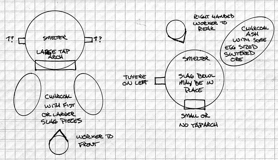
Bottom Extraction <- | -> Top Extraction
Figure 7 - Likely debris fields around a smelter.
Bloom Size and Quality:
Artifact iron blooms from the period of interest are often found as compressed
‘pucks’, in the range of 2 to 12 kg in weight. An ‘average’
bloom is about 4 to 8 kg and often shows a distinctive slice from one edge.
(15) The shape of these blooms has certainly derived from an initial consolidation
immediately as they have been removed from the smelter. Experience from cutting
a number of blooms (and through years at the forge) suggests that an iron master
can judge both the density and rough carbon content of the metallic iron through
the amount of effort required for these processes.
The method as developed here has produced blooms as large as into the 20 kg range. As a rough rule of thumb, the first three hours (including preheat), and approximately 1/3 or more of the total charcoal expenditure, are used to reach the point in the smelter sequence where any bloom at all is starting to form. Obviously making a single large bloom is a far more efficient use of all resources than running two separate smelts to produce two separate ‘half sized’ blooms. When this ability to produce large blooms utilizing smelters of similar size to artifact samples is demonstrated, it raised the question - why are so many of the artifact blooms so much smaller?
The answer may lie not in the iron smelter itself, but with the Norse blacksmith.
Examination of the existing artifact tool sets, although admittedly removed
from the smelting operation, suggests that very large sledge hammers were not
part of the Viking Age tool set. The largest hammer in the Mastermyr find is
3.4 kg (7 1/2 lbs), with the next pair (most certainly single hand hammers)
at 1.8 and 1.6 kg. (16) The largest, fitted with a 85 cm handle (the longest
that would fit in the chest) only compares with the smallest hammer used
during these experiments for consolidation (at 8 lbs / 3.6 kg). Most of the
hammers used for experimental consolidation were in the 10 - 15 lb (4.5 - 6.8
kg) range. Particularly when attempting to work a large, dense bloom, a lighter
hammer simply cannot strike with enough force to affect the mass significantly.
The second factor is related to the problem of physically heating such a large
mass of metal. All the work being described here is undertaken as quickly as
possible, utilizing the initial heat remaining from the smelting process. Once
the bloom approaches a measurement close to that of the diameter of the smelter
itself, even the still hot smelter cannot supply enough heat to raise that mass
back up to effective forging temperatures. In this experimental series, the
largest blooms (in the range of 10 - 20 kg) have not been worked into bars,
exactly because of this same problem of how to reheat them.
One conclusion is that historic blooms have been created in smaller sizes that what could have been easily achieved quite deliberately - specifically for ease in handling, forging and reheating.
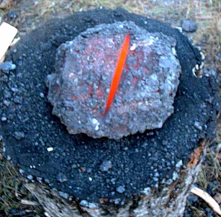
Figure 8 - Classic iron bloom of 6.8 kg on wooden stubb. (Smelt 22)
Conclusions:
After smelt three, an attempt was made to outline the possible experimental
variables that might influence the progress of a successful smelt (17), with
dozens of individual factors suggested. At the time of writing, most of the
major elements have at least been roughly determined : a working smelter design,
a relationship for ore and charcoal particle size, and a determination of effective
air volumes. The team has reached a level of experience where metallic blooms
are predictably created. More work remains in effectively matching reconstructed
Viking Age bellows types into the smelting process. More practice needs to be
acquired in controlling the carbon content of individual blooms.
Above all, it must be clearly stated that the progress of the experiments has
started from a largely theoretical basis, then moved over to concentrate on
a single effective system, and now is in the process of working back towards
a possible historical model. The continuing problems with air delivery, and
the frankly speculative solutions explored, certainly reminds all involved that
these experiments may present a way to effectively smelt using Viking
Age prototypes - but may not represent the way used historically.
Contributors:
An important influence has been repeated workshops with Lee Sauder & Skip Williams of the Rockbridge Bloomery, Lexington VA. Along with Michael McCarthy, the resulting professional association and personal friendship has greatly influenced the experimental series discussed here. Many core ideas recorded here have sprung up at late night group discussions after a long day of smelting and every attempt has been made to attribute individual contributions if at all possible.
Neil Peterson assisted in the preparation of this paper by editing the document.
the DARC Smelt Team:
Neil Peterson, Ken Cook, Kevin Jarbeau, Dave Cox
Assisting:
Sam Falzone, Marcus Burnham, David Robertson, Gus Gissing
Meghan Roberts, Anne Graham, Karen Peterson, Vandy Simpson
These and other members of the Dark Ages
Re-creation Company have formed the core team for many of the experiments
described here. It would have been impossible to mount the individual smelts
without their willing labour. Individuals have also provided their skills in
documenting each experiment and all have suggested improvements as the work
has progressed.
Other Smelt Participants (rough order of participation):
Arne Espelund, Dr. Birgitta Wallace, Mark Pilgram, Kevin Smith
Michael Mahoney, Millard Wyman, Paul Burden, Elizabeth Hendrix,
Dr. Leigh Symonds, Vine Petty, John Burton, John Newman,
Lloyd Johnston, Toby Bush, Brent Cole, Kent Chambers,
Dick Sargent, Peter Martin, Scott Pond, Dr. Ron Ross,
Jake Keen, Michael Nissen
A Special Thanks:
To Royal Oak Charcoal. Royal Oak has generously donated all the charcoal used
for the bulk of these experiments. This continuing series would not have been
possible without their support.
Footnotes:
(1) 'IV Investigations'
KristJan Eldjarn
'The Discovery of a Norse Settlement in America'
Anne Stine Ingstad
Universitetsforlaget - Oslo.,1977
(2) 'A Practical Treatise on the Smelting and Smithing of Bloomery Iron'
Lee Sauder & Skip Williams
Historical Metallurgy, vol. 36 (2), 2002
(3) As analyzed by R. Hansen at Eramet, Prosgrunn in July 2001.
Data received in a personal correspondence from A. Esplund, 25 July 2001.
(4) As demonstrated by A. Espelund during the Parks Canada workshop, June 25-29,
2001.
(5) As analyzed by M. Burham at Sudbury, Ontario in February 2002.
Data received in a personal correspondance from M. Burham, 10 February 2002.
(6) Sauder & Williams, 2002
(7) Copy of internal STELO document, Spring 2005
(8) 'Barshot 20, Technical Data Sheet'
Opta Minerals, Spring 2006
(9) As related by B. Wallace in a series of personal correspondence, Spring
2001
(10) 'The Coated Tyle Furnace'
Lee Sauder and Skip Williams
http://iron.wlu.edu/Coatedtyle%20Construction.htm
(11) From personal correspondance with Kevin Smith, Spring 2005
(12) 'Smelting Enriched Bog Ore in a Low Shaft Bloomery'
Jonathan Thornton, Skip Williams and Aaron Shugar
http://iron.wlu.edu/reports/Eindhoven%20Smelt%20Report.htm
(13) Sauder & Williams, 2002
(14) Experiments with a Slag-Tapping and a Slag Pit Furnace
Anneke Boonstra, Thijs van de Manakker, Wim van Dijk
'Early Iron Production - Archaeology, Technology and Experiments'
Lars Chris. Norbach editor
Historical-Archaeological Experimental Centre, No. 3, 1997
(15) 'Iron in Archaeology - the European Bloomery Smelters'
Radomir Pleiner
Archeologicuy Ustoav Av Cr, 2000
(16) 'The Mastermyr Find - A Viking Age Tool Chest from Gotland'
Greta Arwidsson & Gokstad Berg
Almqvist & Wiksell, 1983
(17) 'The Limits of Experiment'
Darrell Markewitz, with the assistance of Leigh Symonds, 2004
http://www.warehamforge.ca/ironsmelting/consider.html
'Iron Making in a Roman Furnace'
Henry Clara
Britannic, v.2, 203-217, 1971
'The Classification of Early Iron Smelting-Furnaces'
H. F. Cleere
The Antiquaries Journal, v.52, 8-23, 1972
'The Experimental Production of Prehistoric Bar Iron'
Peter Crew
Historical Metallurgy v. 25 no. 1, 1991
'Iron Production in Norway During Two Millennia'
Arne Espelund
Arkentype, 1995
'The Four Phases: Carbon - Gas - Slag - Metal and their Interaction in Bloomery Iron making'
Are Espelund
in 'Prehistoric and Medieval Direct Iron Smelting in Scandinavia and Europe'
Lars Chris. Norbach editor
Aarhus University Press, 2003
'Metallurgy and Metalworking in Ancient Russia
B.A. Kolchin
Translated by the Israel Program for Scientific Translations, 1967 (original 1953)
'Experimental Iron Smelting from the Viking Age'
Darrell Markewitz
the Wareham Forge, 2007
'Early Iron Production - Archaeology, Technology and Experiments'
Lars Chris. Norbach editor
Historical-Archaeological Experimental Centre, No. 3, 1997
'Ore, fire, hammer, sickle : Iron production in Viking Age and Early Medieval Iceland'
Kevin Smith
De Rye Metallica: AVISTA Studies, v 4,183-206, 2005
'The Early History of Metallurgy in Europe'
R. F. Tylecote
Longman, 1987
'Metallurgy in Archaeology'
R. F. Tylecote
Edward Arnold, 1962
Those wishing to see the detailed notes and photographs recording the sequence of any individual experiment are referred to the web based documentation at: